Blade Gap Setting for Blade Cutter Assembly

a cutting head and blade technology, applied in the direction of mechanical means, instruments, manufacturing tools, etc., can solve the problems of poor ergonomics, health and safety, and dull blade edge sharpness

Inactive Publication Date: 2012-11-01
FRITO LAY NORTH AMERICA INC
View PDF2 Cites 14 Cited by
  • Summary
  • Abstract
  • Description
  • Claims
  • Application Information

AI Technical Summary

Problems solved by technology

First, the device requires reference surfaces to bear against the cutting edge of the blade, which can tend to dull the sharpness of the blade edge.
Second, the device needs to be held in place manually by the operator during the measurement process so as to locate the reference points on the cutter assembly. This leads to poor ergonomics because it is difficult for the operator to maintain the device in the require location while reading the measured blade gap and adjusting the clamping of the blade to achieve the desired blade gap. In addition, the manual holding of the device introduces health and safety issues due to the potential for inadvertent operator contact with the adjacent blade cutting edge in the series of annularly located blades when locating and holding the device in position.

Method used


Image

  • Blade Gap Setting for Blade Cutter Assembly
  • Blade Gap Setting for Blade Cutter Assembly
  • Blade Gap Setting for Blade Cutter Assembly

Examples


Embodiment Construction

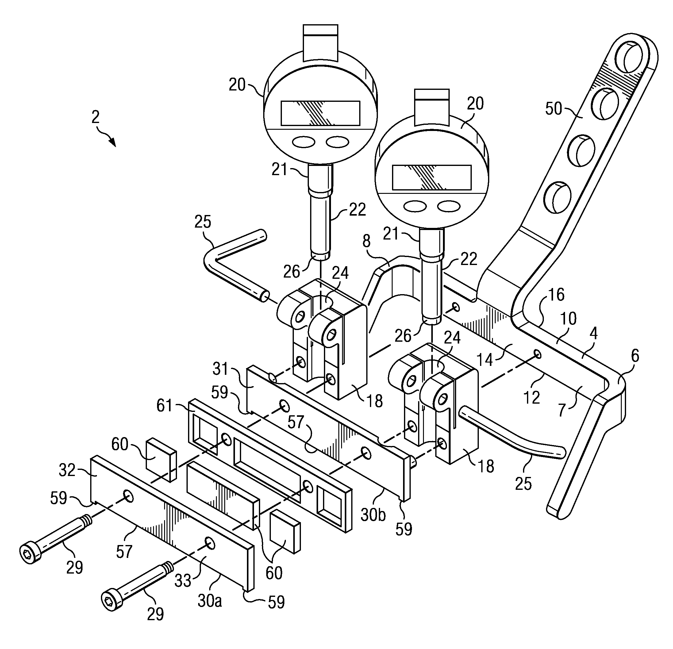
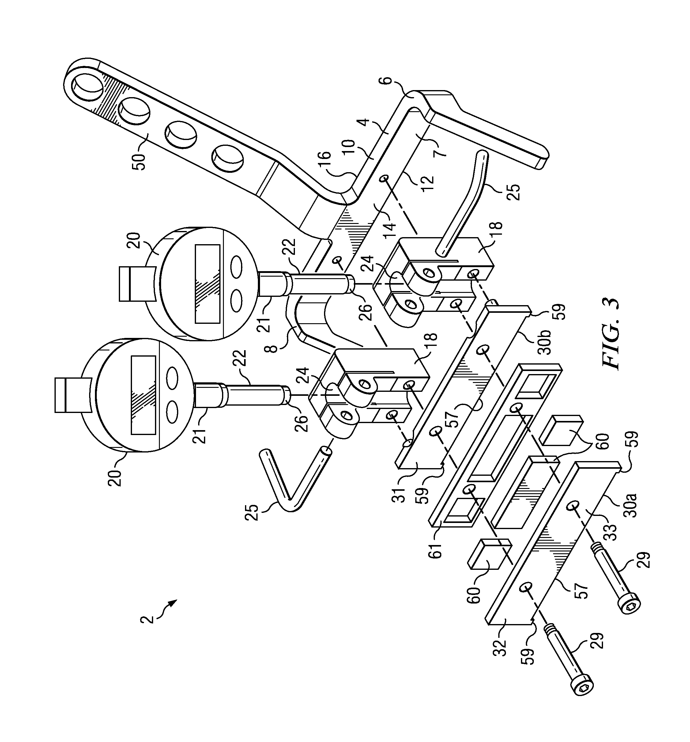
[0046]Referring to FIGS. 3 to 5, a blade gap setting device, designated generally as 2, in accordance with an embodiment of the present invention is illustrated. The device 2 includes a longitudinally extending elongate body 4 which is rigid. The body 4 is typically composed of a metal such as stainless steel. The longitudinal body 4 extends between first and second opposed ends 6, 8. The body 4 includes a support portion 7 which has an upper face 10, a lower face 12, a front side 14 and a rear side 16. Located inwardly of a respective end 6, 8 and fitted to the front side 14 are a pair of mountings 18 of the body 4, each mounting 18 adapted to mount a respective depth micrometer 20 having a displaceable spindle 22. The mounting 18 includes a hole 24, or channel as illustrated, extending downwardly there through to permit the depth micrometer 20 to be removably inserted into the hole 24. This mounts the depth micrometer 20 to the body 4 with a free end 26 of the displaceable spindle...


PUM


Abstract

A blade gap setting device for attachment to a blade holder of a blade cutter assembly has an elongate body with an upper surface and a lower surface and at least one mounting for a depth micrometer having a displaceable spindle. The depth micrometer is installed through a channel of the mounting, with a free end of the displaceable spindle being exposed beneath the mounting. The device also has a first rounded front reference surface located at a position in front of the mounting, a second front reference surface extending downwardly from the body, and a third lower reference surface below the mounting or spindle. The reference surfaces serve as contact points to bear against interior portions of the blade cutter assembly; in particular, the blade holder and a top surface of the blade.

Description

CROSS-REFERENCE TO RELATED APPLICATION[0001]This is a continuation-in-part and claims filing priority rights with respect to currently pending U.S. patent application of application Ser. No. 13 / 097,278, filed Apr. 29, 2011. The technical disclosures of all of the above-mentioned applications are hereby incorporated herein by reference.BACKGROUND[0002]The present invention relates to a blade gap setting device for a potato chip cutting head and to a method of setting the blade gap on a potato chip cutting head.DESCRIPTION OF THE PRIOR ART[0003]It is well known to employ a rotary cutting apparatus for cutting potatoes into fine slices for the manufacture of potato chips. A well-known cutting apparatus, which has been used for more than 50 years, comprises an annular-shaped cutting head and a central impeller assembly coaxially mounted for rotation within the cutting head to deliver food products, such as potatoes, radially outwardly toward the cutting head. A series of knives is mount...

Claims


Application Information

Patent Timeline
Patent Type & Authority Applications(United States)
IPC IPC(8): G01B1/00G01B3/28
CPCB23Q17/2216B23Q17/0919
Inventor ORNELAZ, JR., RICHARD DECENA
Owner FRITO LAY NORTH AMERICA INC
Why Eureka
Try Eureka