Ratchet wrench

a ratchet wrench and ratchet technology, applied in the field of ratchet wrenches, can solve the problems of not being convenient to use, drawing back the conventional ratchet wrench,

Active Publication Date: 2012-11-01
LIN YI HUNG
View PDF5 Cites 7 Cited by
  • Summary
  • Abstract
  • Description
  • Claims
  • Application Information

AI Technical Summary

Problems solved by technology

However, there is a drawback of the conventional ratchet wrench 1.
For a user, it is not convenient

Method used


Image

  • Ratchet wrench
  • Ratchet wrench
  • Ratchet wrench

Examples


Embodiment Construction

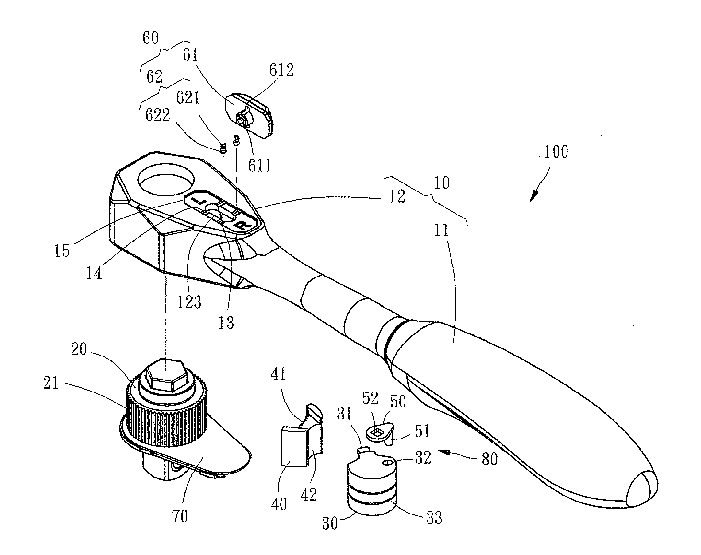
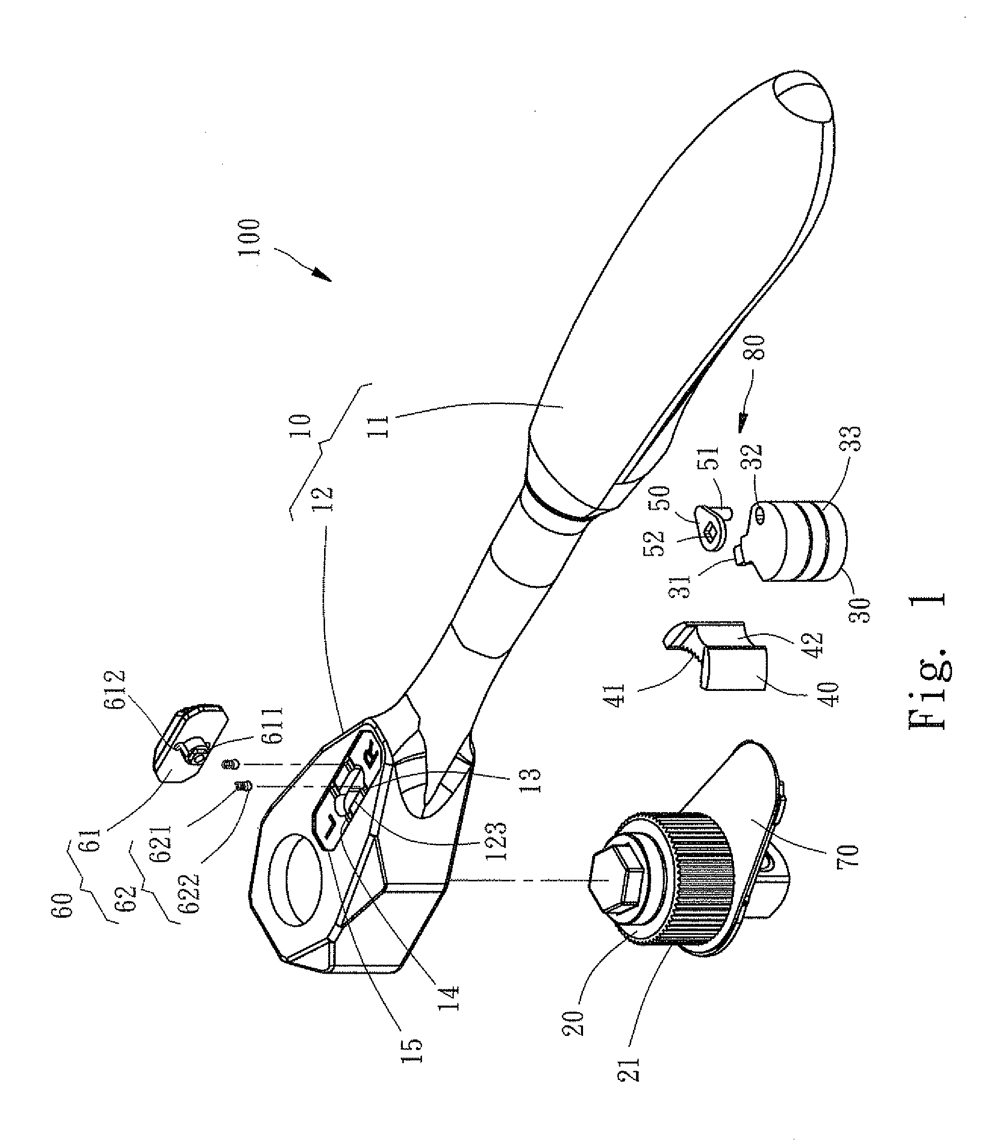
[0016]Referring to FIGS. 1 to 7, a ratchet wrench 100 in accordance with the invention comprises a main body 10, a drive gear and socket combination 20, a pivotal unit 30, a reversing pawl 40, a follower member 50, and a reversing button assembly 60. Each component will be discussed in detail below.

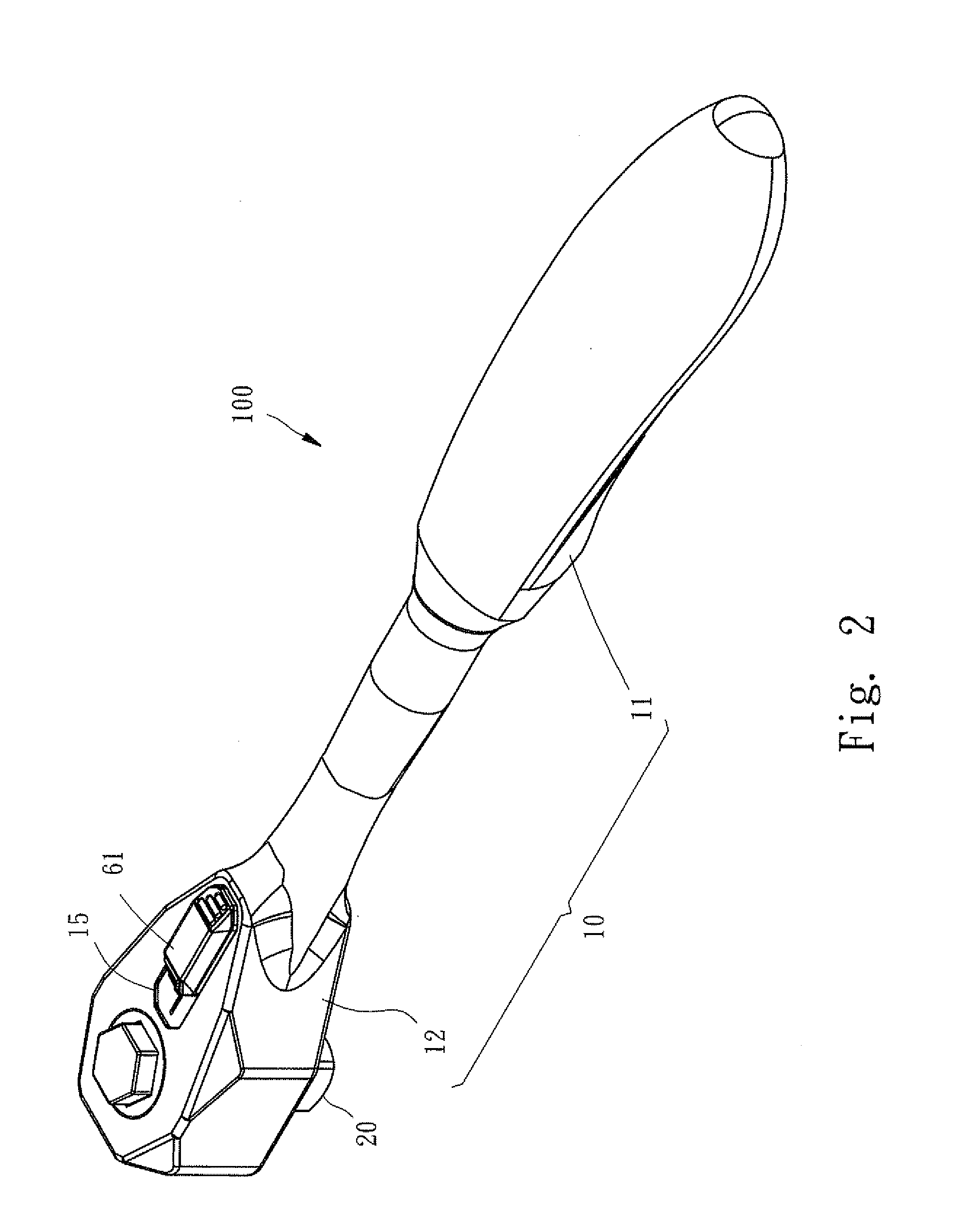
[0017]The main body 10 comprises an elongated handle 11 to held by the hand, and a wrench head 12 integrally formed therewith. In the wrench head 12 there are provided a forward first cavity 121 and a rear second cavity 122 communicating therewith. An opening 123 is formed on top of the second cavity 122. An axial, elongated recess 15 is formed on top the wrench head 12 on the opening 123. A rear, interrupted first groove 13 and a forward, interrupted second groove 14 are formed on the recess 15. The first groove 13 and the second groove 14 are spaced by a distance.

[0018]The drive gear and socket combination 20 is rotatably provided in the first cavity 121 and comprises teeth 21 on its cy...


PUM


Abstract

A ratchet wrench includes a handle; a wrench head comprising a first cavity and a second cavity communicating therewith; a drive gear and socket combination rotatably disposed in the first cavity and comprising surface teeth; a reversing pawl comprising pawl teeth on one surface, the pawl teeth meshed with the teeth of the drive gear and socket; a pivotal unit pivotably disposed in the second cavity, the pivotal unit urging against the other surface of the reversing pawl and being adapted to reciprocally pivot about the reversing pawl; and a reversing button assembly moveably disposed on the wrench hand and aligned with an axial direction of the handle. The reversing button assembly is adapted to manually move along a straight line to activate the pivotal unit which pivots the reversing pawl so as to permit the drive gear and socket combination to rotate clockwise or counterclockwise.

Description

BACKGROUND OF THE INVENTION[0001]1. Field of the Invention[0002]The invention relates to ratchet wrenches and more particularly to a ratchet wrench having an axially moveable reversing button for ease of switching between clockwise driving and counterclockwise driving of the ratchet head.[0003]2. Description of Related Art[0004]A conventional ratchet wrench 1 s shown in FIG. 8 and comprises a handle 2 and a reversing lever 3 capable of leftward or rightward pivoting to switch between clockwise driving and counterclockwise driving of the ratchet head.[0005]However, there is a drawback of the conventional ratchet wrench 1. In detail, the reversing lever 3 is capable of only either leftward or rightward pivoting. For a user, it is not convenient in use since the finger has to perform a leftward or rightward pivoting operation in an awkward way. Thus, the need for improvement still exists.SUMMARY OF THE INVENTION[0006]It is therefore one object of the invention to provide a ratchet wren...

Claims


Application Information

Patent Timeline
IPC IPC(8): B25B13/46
CPCB25B13/463
Inventor LIN, YI-HUNG
Owner LIN YI HUNG
Why Eureka
Try Eureka