RFID Microstip Interrogator Antenna System

a microstip and antenna technology, applied in the field of wireless communication, can solve the problems of mounting hardware that increases the cost of mounting, the cost of installation can be greatly over the cost of hardware, and the cost of rfid antennas can be expensiv

Inactive Publication Date: 2012-11-01
DEAVOURS DANIEL D
View PDF6 Cites 4 Cited by
  • Summary
  • Abstract
  • Description
  • Claims
  • Application Information

AI Technical Summary

Benefits of technology

[0014]The cord of the hanger kit provides approximately 1.5 inches of relief from the wire mesh. This allows the antenna to reside in the approximately three inch region below the industrial racking that is protected by the front cross member of the rack. Thus, to be disturbed by placing product in or taking product out of the rack, an operator must, for example, pl

Problems solved by technology

The cost of RFID antennas can be expensive, commonly ranging from $30 to $350.
Mounting hardware further increases the cost, and in some instances, the cost of installation can greatly exceed the cost of the hardware.
Thus, the cost of the antenna, mounting hardware, and cost of installation are a significant source of inefficiency in many modern UHF RFID systems.
The current methods of manufacturing microstrip antennas are significantly complex and have a number of limitations.
The antennas tend to be relatively heavy, weighing between 1 to 4 pounds (0.5 to 2 kg), which affect

Method used


Image

  • RFID Microstip Interrogator Antenna System
  • RFID Microstip Interrogator Antenna System
  • RFID Microstip Interrogator Antenna System

Examples


Embodiment Construction

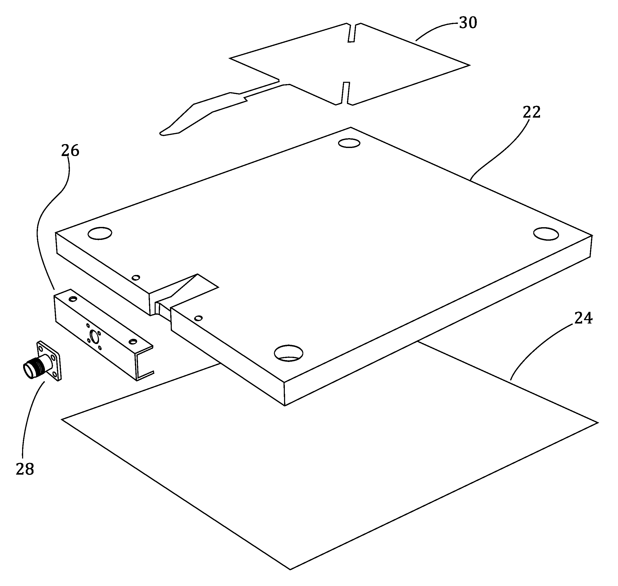
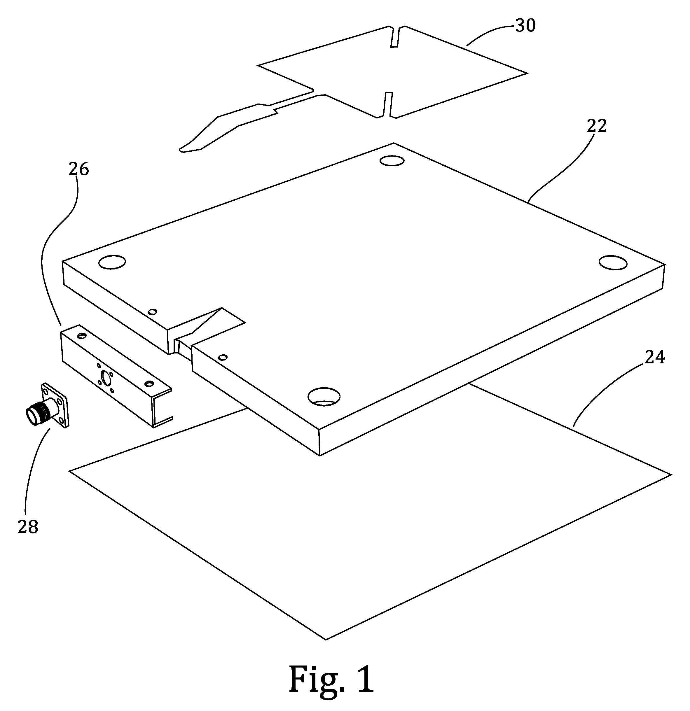
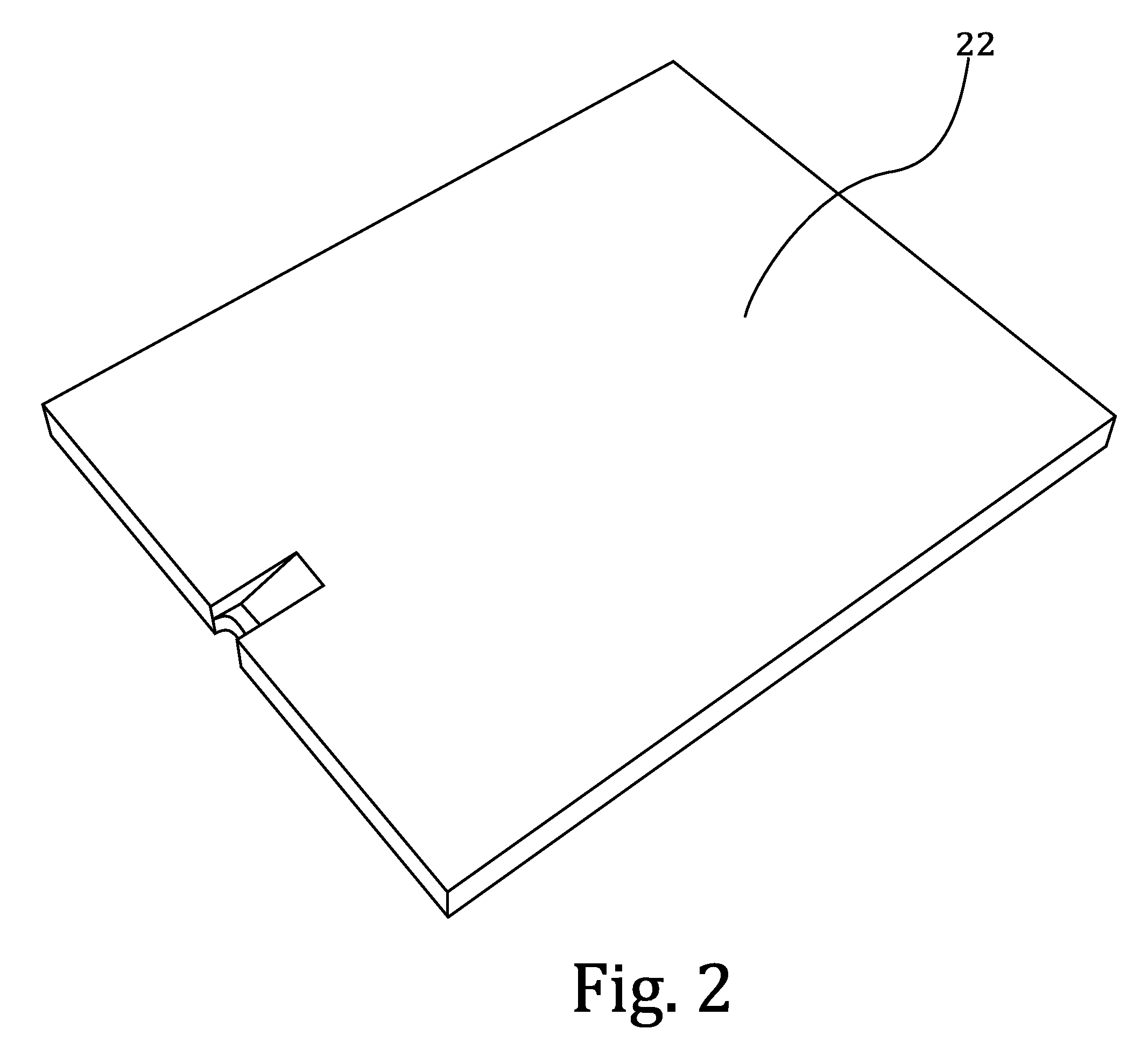
[0025]With reference to the figures, an RFID microstrip interrogator antenna system is herein described, the embodiment of the invention consists of the following elements: an base antenna (20), an optional enclosure (40), and an optional hanger kit (60). Referring to FIG. 1, the base antenna consists of: the pattern (30), dielectric substrate (22), ground plane (24), bracket (26), and RF connector (28). The enclosure consists of a folding carton (40). Referring to FIG. 8, the hanger kit comprises four units, each consisting of: a length of shock cord (64), hook (66), knot (68), and crimp (70). Each of these is described below.

Function

[0026]The current invention functions as a microstrip antenna. Signal originates externally and couples through a coaxial cable and coaxial cable connector, which mates to the RF connector (28). The signal ground couples to the bracket (26), which is coupled to the ground plane (24). The signal couples from the connector pin (29) to the transmission li...


PUM


Abstract

The present invention overcomes the above-described and other problems by providing an improved edge-fed microstrip patch antenna, a dielectric substrate with integrated ground plane and enclosure that with a printable surface. An RFID microstrip patch antenna (21) system produces an antenna that is significantly less expensive to manufacture and install than existing commercial solutions. In doing so, the present invention enables the use of commodity, low cost products such as corrugated paperboard foils and extruded polystyrene and assembly methods such as graphics printing.

Description

RELATED APPLICATIONS[0001]The present non-provisional patent application is related to and claims priority benefit of an earlier-filed provisional patent application titled Composition and Enclosure of Inexpensive Microstrip Antenna, Ser. No. 61 / 481,029, filed Apr. 29, 2011. The identified earlier-filed application is hereby incorporated by reference into the present application.FIELD OF INVENTION[0002]This invention pertains to the area of wireless communications, more specifically to RF communications, even more specifically to radiofrequency identification (RFID) in the ultra high frequency (UHF) range, even more specifically a patch-like antenna for transmitting and receiving RF communications for UHF RFID, and most specifically to a low-cost implementation of such an antenna and method for making the same. While UHF RFID is the primary intended purpose of the invention, the invention may be used in other applications with a comparable range of frequency is required (e.g., 300 M...

Claims


Application Information

Patent Timeline
IPC IPC(8): H01Q1/36H01Q1/48
CPCH01Q1/2216H01Q9/0428H01Q1/38
Inventor DEAVOURS, DANIEL D.
Owner DEAVOURS DANIEL D
Why Eureka
Try Eureka