Safety pen needle assembly

Active Publication Date: 2012-11-01
EMBECTA CORP
View PDF2 Cites 32 Cited by
  • Summary
  • Abstract
  • Description
  • Claims
  • Application Information

AI Technical Summary

Benefits of technology

[0003]In one aspect, a safety pen needle assembly is provided which includes a hub, a needle fixed to a transverse wall of the hub, and a shield formed to at least partially telescope over the hub. An outer ablumenal surface of the hub and an inner lumenal surface of the shield are formed with cooperating thread elements to permit relative rotation between the hub and the shield. In an initial state, the cooperating thread elements are in threaded engagement with the shield being positioned relative to the hub with a distal end of the shield sidewall being located distally of a distal end of the needle. Also, in the initial state, the shield and the hub are configured with

Problems solved by technology

As such, a user may inadvertently suffer a needle stick during mounting.
Transmission of biological material or disease is not a concern with the needle being in a clea

Method used


Image

  • Safety pen needle assembly
  • Safety pen needle assembly
  • Safety pen needle assembly

Examples


Embodiment Construction

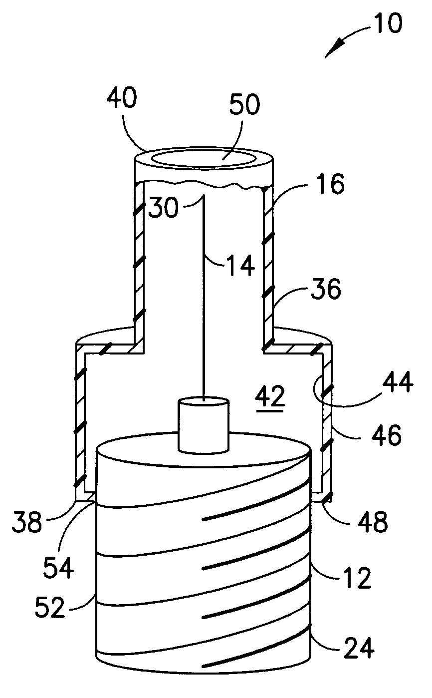
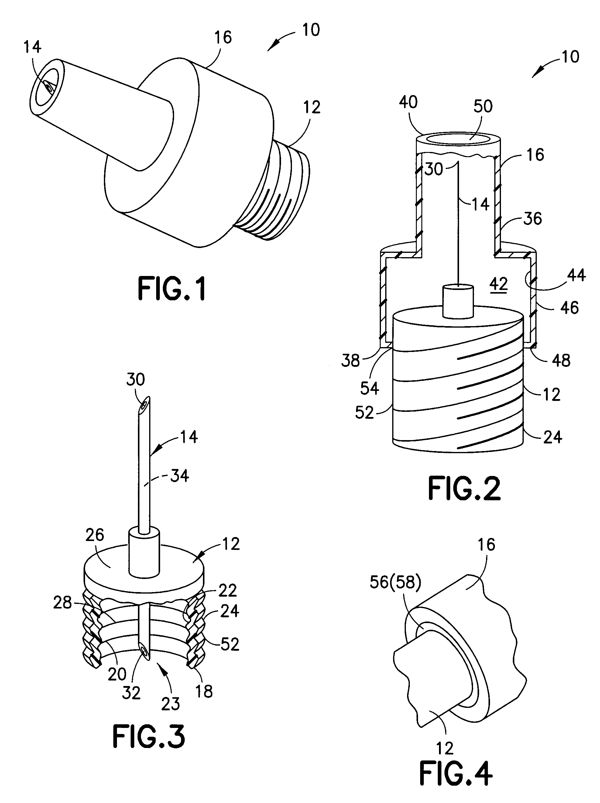
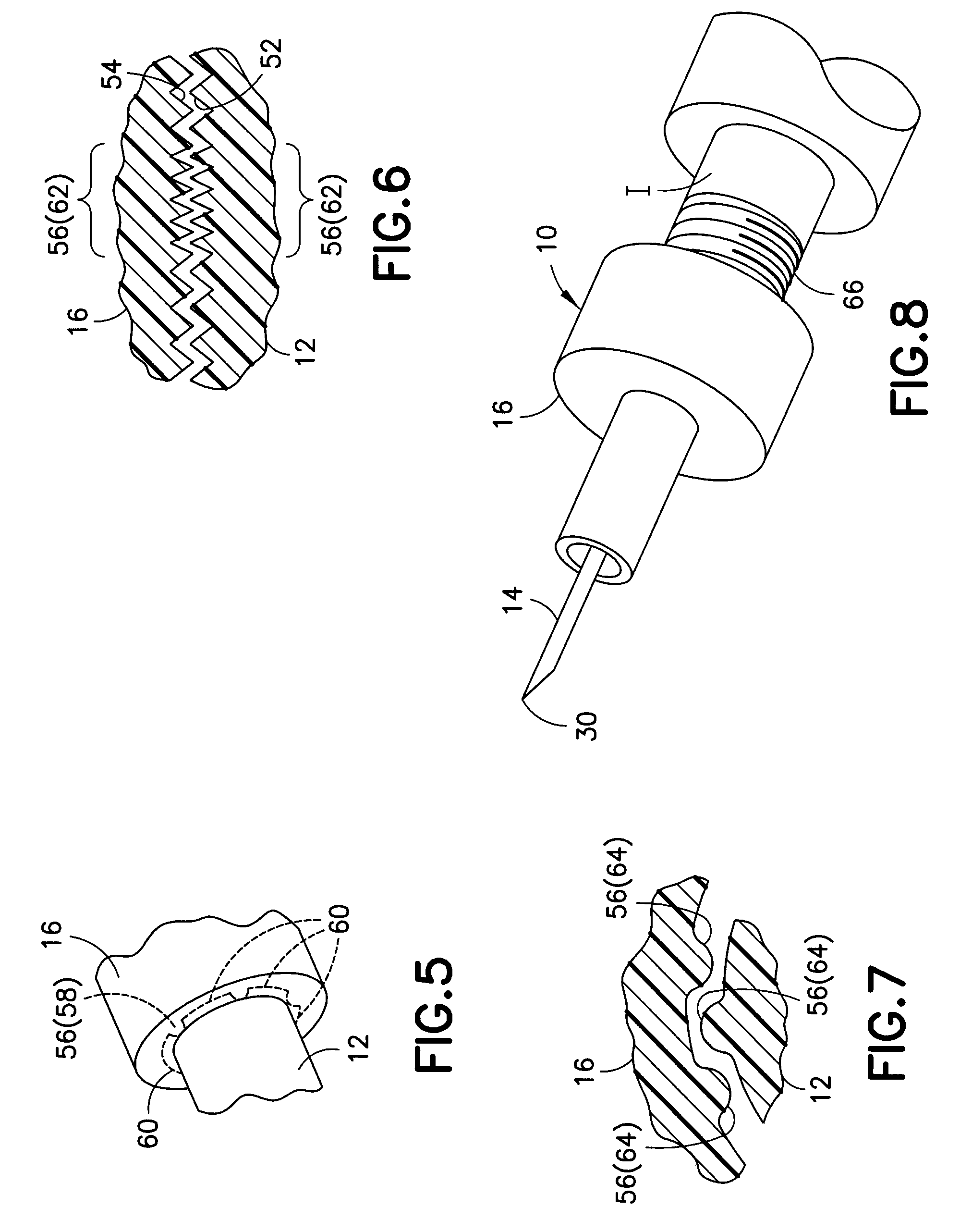
[0023]With reference to the Figures, a safety pen needle assembly 10 is shown which generally includes a hub 12, a needle 14, and a shield 16. The safety pen needle assembly 10 is formed for mounting onto various injector bodies I and is particularly well-suited for use with pen injectors.

[0024]The hub 12 includes a tubular side wall 18 which defines a lumen 20, with an inner lumenal surface 22 and an outer ablumenal surface 24, and a proximal opening 23. A transverse wall 26 extends transversely from the side wall 18 to overlap at least a portion of the lumen 20. Preferably, the transverse wall 26 overlaps completely the lumen 20. The lumenal surface 22 is formed with features 28 for mounting the hub 12 onto the injector body I. Preferably, the mounting features 28 is a thread element formed for threaded engagement with a cooperating thread on the injector body I. As will be appreciated by those skilled in the art, the features 28 may include additional or different features, such ...


PUM


Abstract

In one aspect, a safety pen needle assembly is provided which includes a hub, a needle fixed to a transverse wall of the hub, and a shield formed to at least partially telescope over the hub. An outer ablumenal surface of the hub and an inner lumenal surface of the shield are formed with cooperating thread elements to permit relative rotation between the hub and the shield. In an initial state, the cooperating thread elements are in threaded engagement with the shield being positioned relative to the hub with a distal end of the shield sidewall being located distally of a distal end of the needle. Also, in the initial state, the shield and the hub are configured with a rotation-resistance arrangement which inhibits relative rotation between the hub and the shield. The rotation-resistance arrangement is surmountable to allow relative rotation between the hub and the shield with an at least threshold amount of torque being applied, the threshold amount of torque being greater than required to mount the pen needle assembly onto an injector body. Advantageously, with the subject invention, a safety pen needle assembly can be provided having a shield threaded onto a hub with the assembly being mountable with the needle being in a shielded state. This minimizes the possibility of needle stick during mounting of the safety pen needle assembly.

Description

FIELD OF THE INVENTION[0001]This invention relates to safety pen needle assemblies.BACKGROUND OF THE INVENTION[0002]Safety pen needle assemblies are well known in the art for use with medical injectors, particularly pen injectors. Shielding of a used needle post-injection is provided by such devices. Various configurations for shielding are available, including a displaceable shield relative to the needle hub. U.S. Pat. No. 5,964,731 to Kovelman discloses a shield threaded onto a needle hub. With this configuration, however, the shield must be in its most extreme lowest position, wherein the needle is maximally exposed, for mounting onto a medical injector. As such, a user may inadvertently suffer a needle stick during mounting. Transmission of biological material or disease is not a concern with the needle being in a clean state; however, with a practitioner suffering a needle stick, the pen needle assembly must be disposed of since the needle can not be used subsequently on a pati...

Claims


Application Information

Patent Timeline
IPC IPC(8): A61M5/32
CPCA61M5/3243A61M5/347A61M5/3202A61M2005/3254A61M2005/3247
Inventor LIMAYE, AMIT UDAY
Owner EMBECTA CORP
Why Eureka
Try Eureka