Microelectromechanical systems (MEMS) resonators and related apparatus and methods

a microelectromechanical and magnetic technology, applied in microstructural devices, microstructural technology, generators/motors, etc., can solve problems such as difficult integration of present-day products, as well as of tomorrow's products of even smaller sizes

Active Publication Date: 2012-11-08
ANALOG DEVICES INC
View PDF8 Cites 72 Cited by
  • Summary
  • Abstract
  • Description
  • Claims
  • Application Information

AI Technical Summary

Problems solved by technology

However, conventional fabrication and encapsulation methods limit packaged quartz crystal resonators to a size of about 2.5 mm×2.0 mm, making their integration with present-day products, as well as tomorrow's products of even smaller sizes, difficult.

Method used


Image

  • Microelectromechanical systems (MEMS) resonators and related apparatus and methods
  • Microelectromechanical systems (MEMS) resonators and related apparatus and methods
  • Microelectromechanical systems (MEMS) resonators and related apparatus and methods

Examples


Embodiment Construction

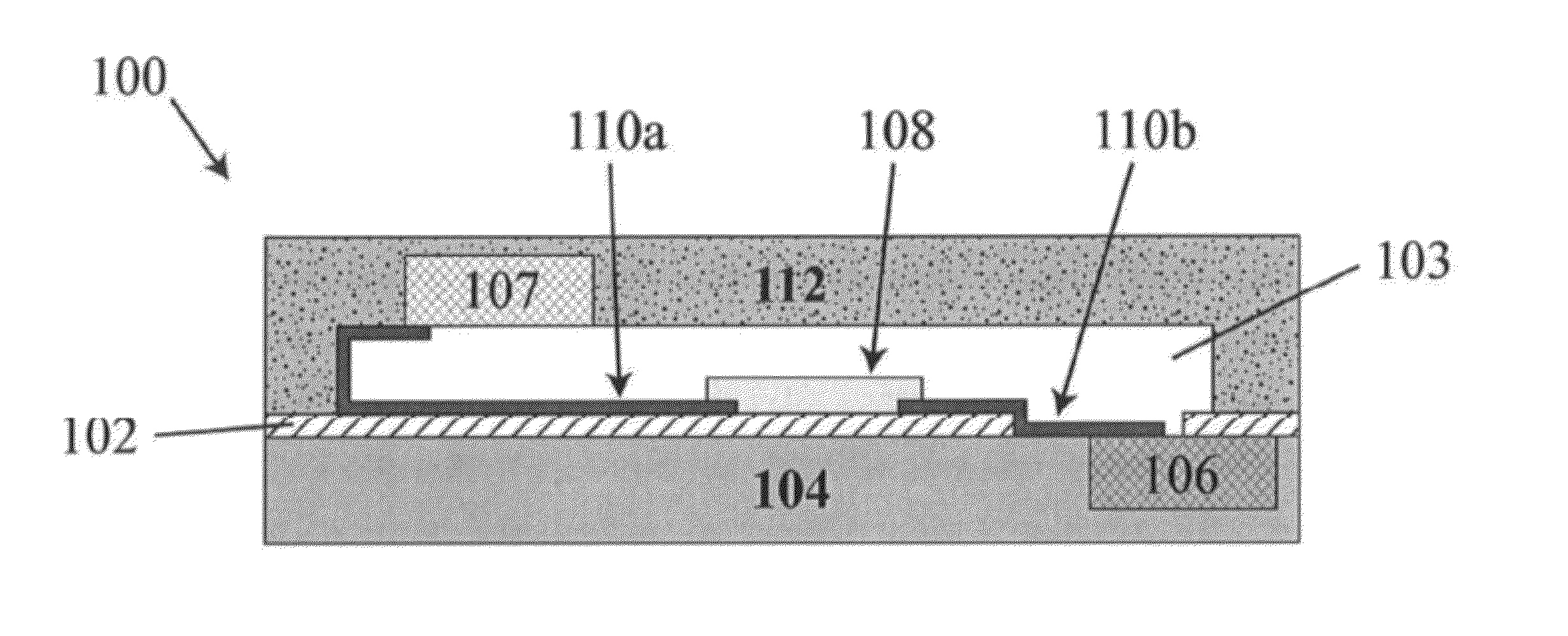
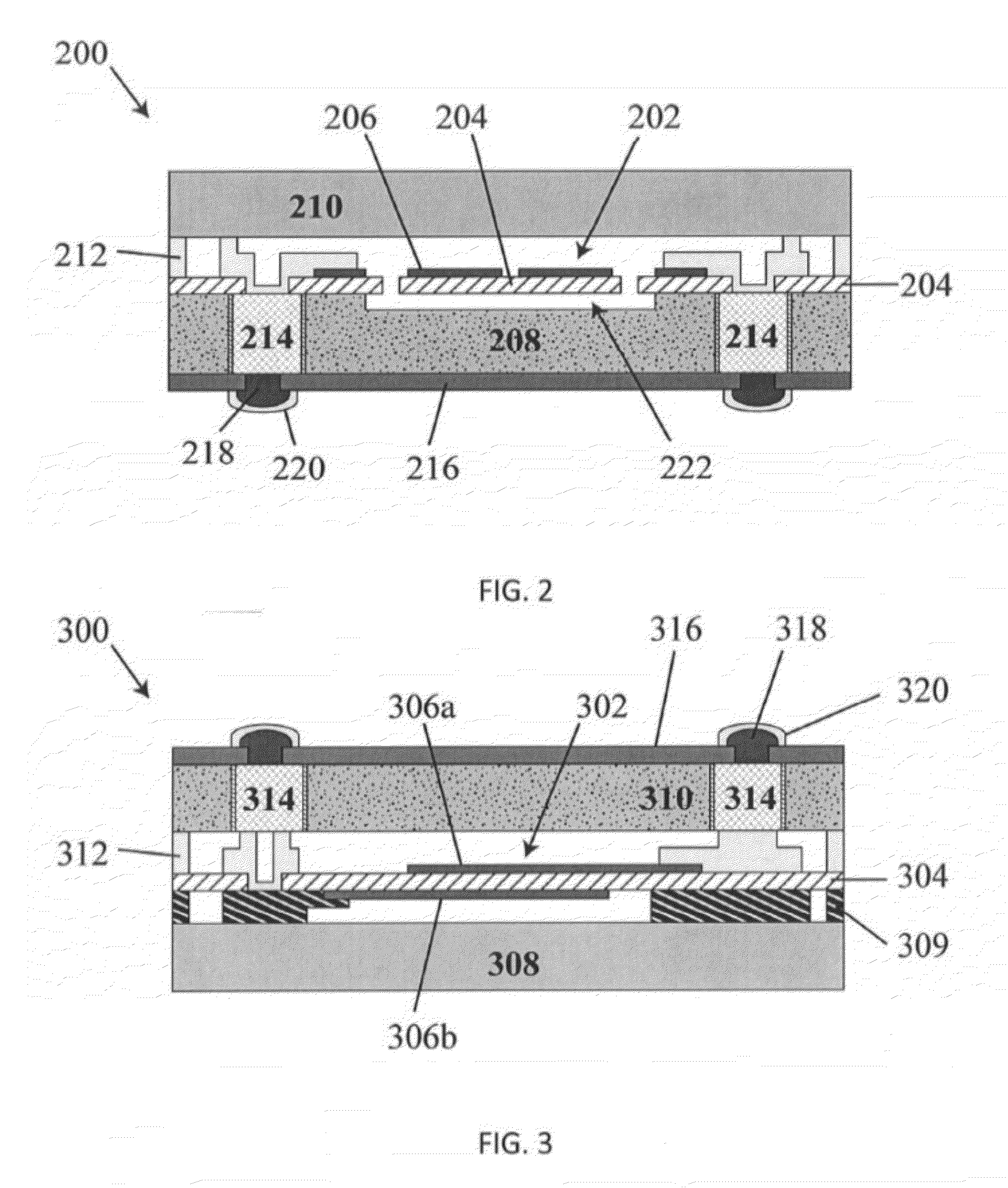
[0030]Device structures including piezoelectric materials integrated with substrates are described, as well as methods of forming the same. In some embodiments, the piezoelectric device structures include single crystal piezoelectric resonators integrated with one or more substrates, for example to form an engineered substrate. One or more of the substrates may include circuitry coupled to the piezoelectric device structures, for example to control operation of the piezoelectric device structure, and / or to detect / sense operation of the piezoelectric device structure. The piezoelectric device structures may be fabricated by bonding a wafer of piezoelectric material to a substrate wafer, and then forming the piezoelectric device structure from the wafer of piezoelectric material. In some embodiments, the piezoelectric material is quartz, which is bonded to a silicon substrate to form an engineered substrate. The piezoelectric device structure may be a quartz resonator formed from the ...


PUM


Abstract

Devices having piezoelectric material structures integrated with substrates are described. Fabrication techniques for forming such devices are also described. The fabrication may include bonding a piezoelectric material wafer to a substrate of a differing material. A structure, such as a resonator, may then be formed from the piezoelectric material wafer.

Description

RELATED APPLICATIONS[0001]The present application claims the benefit under 35 U.S.C. §120 as a continuation-in-part of U.S. patent application Ser. No. 12 / 750,768, filed Mar. 31, 2010 under Attorney Docket No. G0766.70009US01 and entitled “Integration of Piezoelectric Materials with Substrates,” which is hereby incorporated herein by reference in its entirety. U.S. patent application Ser. No. 12 / 750,768 claims priority under 35 U.S.C. §119(e) to U.S. Patent Application Ser. No. 61 / 165,405, filed Mar. 31, 2009 under Attorney Docket No. G0766.70009US00 and entitled “Integration of Piezoelectric Materials With Substrates”, which is hereby incorporated herein by reference in its entirety.[0002]The present application also claims the benefit under 35 U.S.C. §120 as a continuation-in-part of U.S. patent application Ser. No. 12 / 781,076, filed May 17, 2010 under Attorney Docket No. G0766.70008US01 and entitled “Methods And Apparatus For Temperature Control Of Devices And Mechanical Resonati...

Claims


Application Information

Patent Timeline
Patent Type & Authority Applications(United States)
IPC IPC(8): H01L41/053
CPCH03H3/007H03H9/02007H03H9/02244H01L41/053H03H2009/241B81B3/0018H02N1/006H03H9/02535H01L2224/11H01L2224/48091H10N30/88
Inventor CHEN, DAVID M.KUYPERS, JAN H.MOHANTY, PRITIRAJSCHOEPF, KLAUS JUERGENZOLFAGHARKHANI, GUITIGOODELLE, JASONREBEL, REIMUND
Owner ANALOG DEVICES INC
Why Eureka
Try Eureka