
System and method of dynamic regulation of real power to a load

a dynamic regulation and load technology, applied in the field of ac motors, can solve the problems of inability to perform automatic programming of the drive itself, waste of energy, and inefficient operation of the motor drive system, and achieve the effect of stable motor operating conditions and additional energy savings

Active Publication Date: 2012-11-08
EATON INTELLIGENT POWER LIMITED
View PDF5 Cites 27 Cited by
  • Summary
  • Abstract
  • Description
  • Claims
  • Application Information

AI Technical Summary

Benefits of technology

[0008]It would therefore be desirable to design a system and method for dynamically adjusting the V/Hz operating curve of an AC motor drive during motor operation to minimize the motor input real power and achieve ad

Problems solved by technology

Therefore, the V / Hz curve settings often result in wasted energy and inefficient operation of the motor drive system, especially the motor and its connected load.
Although some motor drives may allow a user to alter the V / Hz curve by, for example, adjusting the start, middle, and / or end points of the V / Hz curve, such programming cannot be performed automatically by the drive itself and may be completed only when the motor is shutdown.
This is particularly true if the operator commissioning the drive does not fully understand the load profile of the motor application where the drive is installed.
During the majority of the year, however, the load percentage of the pump motor can be very low.
Using a second order V / Hz curve in this application may be risky because the second order V / Hz curve may not provide enough torque when a heavy rain event occurs.
Thus, there may be little incentive for the operator who commissions the drive to select a different V / Hz curve setting for energy savings over the standard linear V / Hz curve settings.

Method used


Image

  • System and method of dynamic regulation of real power to a load
  • System and method of dynamic regulation of real power to a load
  • System and method of dynamic regulation of real power to a load

Examples


Embodiment Construction

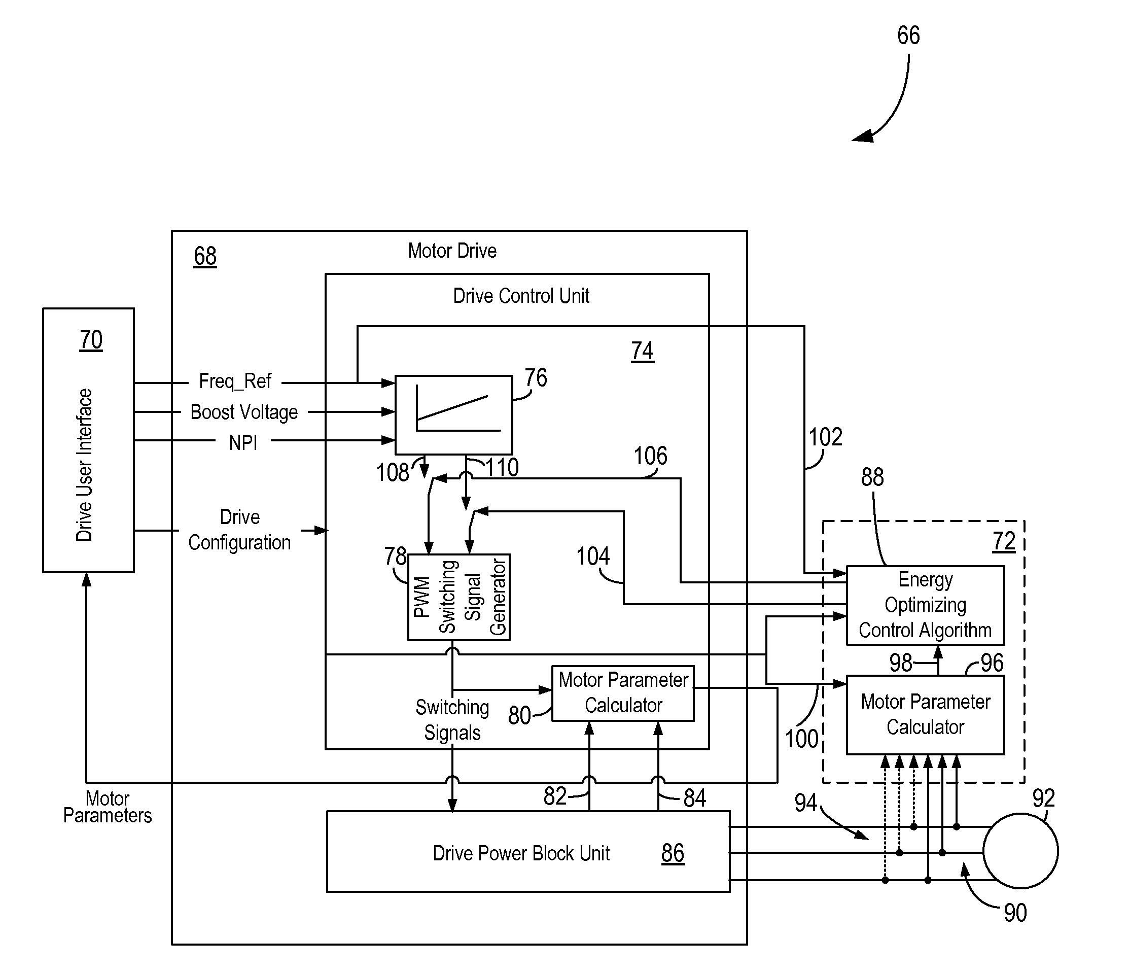
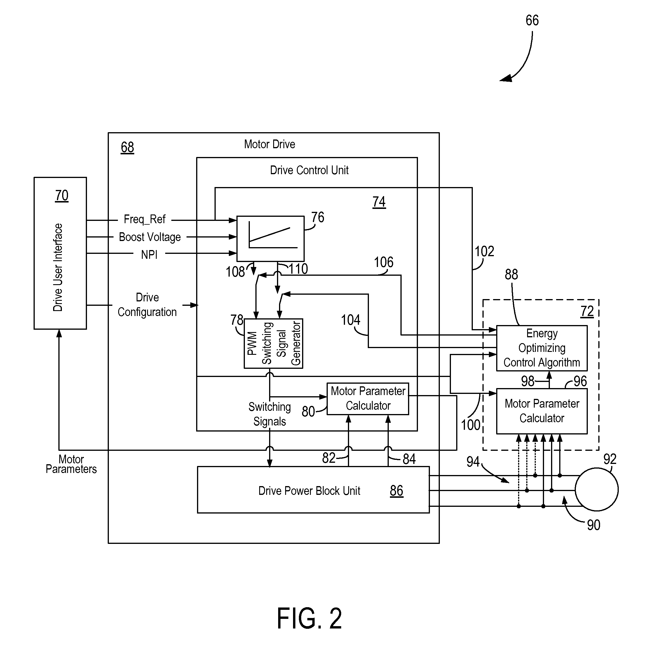
[0029]Several embodiments of the invention are set forth that relate to a system and method of controlling an AC motor drive connected to a load that overcomes the aforementioned drawbacks. These embodiments of the invention are directed to an energy-optimizing control system for open-loop motor drives encompassing a plurality of structures and control schemes.

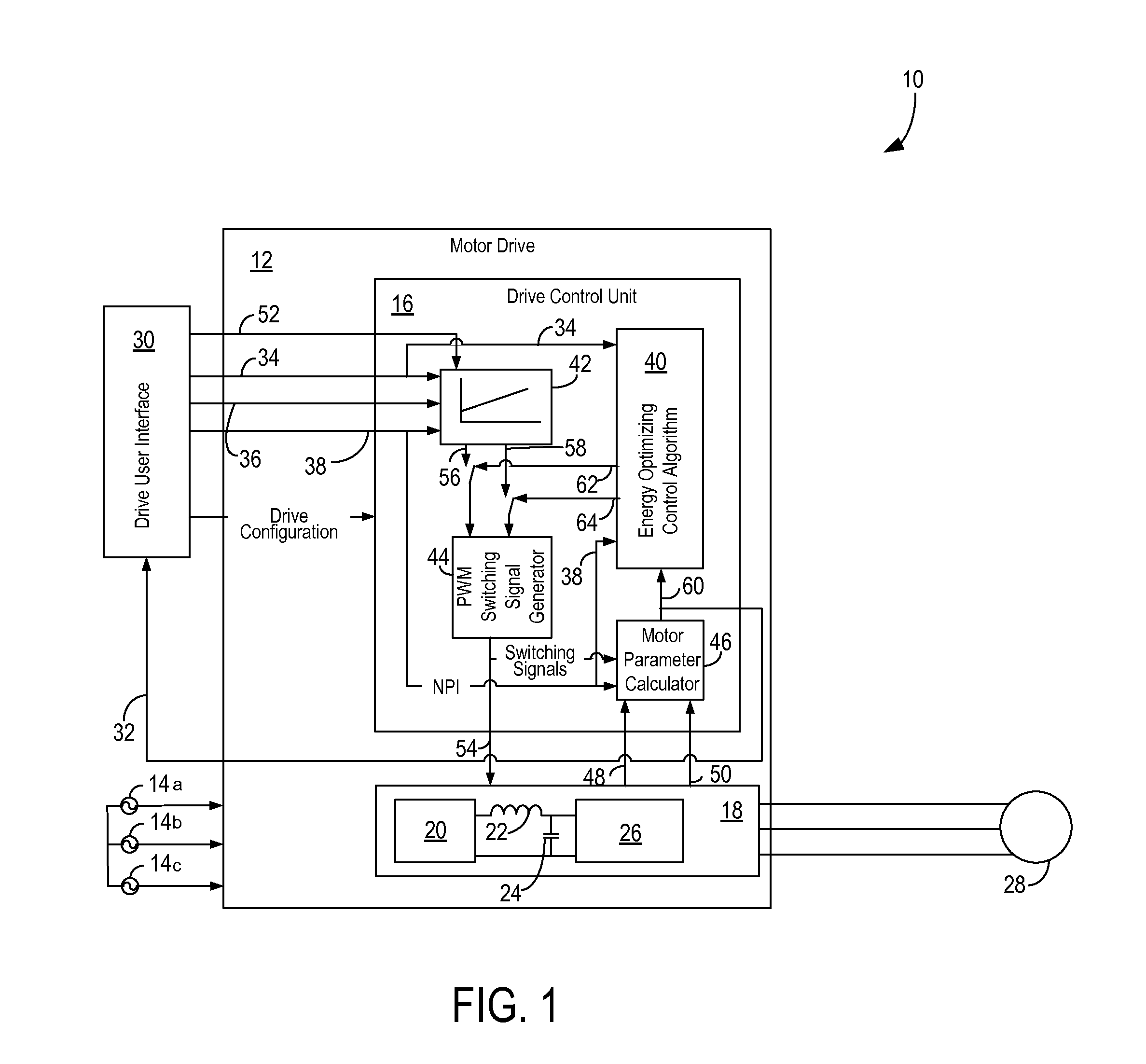
[0030]A general structure of a motor drive system 10 and an associated AC motor drive 12 is shown in FIG. 1. The motor drive 12 may be configured, for example, as an adjustable speed drive designed to receive a three-phase AC power input 14a-14c, rectify the AC input, and perform a DC / AC conversion of the rectified segment into a three-phase alternating voltage of variable frequency and amplitude that is supplied to a load. According to one embodiment, a drive control unit 16 may be integrated within motor drive 12 and function as part of the internal logic of motor drive 12. Alternatively, drive control unit 16 may be embodie...


PUM


Abstract

A system and method for controlling an AC motor drive includes a control system programmed with an algorithm configured to optimize operation of the motor drive. Specifically, the control system is programmed to input an initial voltage-frequency command to the drive. The initial voltage-frequency command includes a voltage reference and a frequency reference corresponding to an operating point of an initial voltage / frequency (V / Hz) curve. The control system monitors a real-time output of the drive, modifies the voltage reference based on the real-time output of the drive, and transmits a modified voltage-frequency command to the drive. The modified voltage-frequency command corresponds to an operating point of a modified V / Hz curve defined by the modified voltage reference and the initial V / Hz curve.

Description

CROSS-REFERENCE TO RELATED APPLICATION[0001]The present invention is a continuation-in-part of and claims the benefit of U.S. Non-Provisional application Ser. No. 12 / 541,320, filed Aug. 14, 2009, which claims the benefit of U.S. Provisional Application Ser. No. 61 / 186,287, filed Jun. 11, 2009, the disclosures of which are incorporated herein by reference.BACKGROUND OF THE INVENTION[0002]The present invention relates generally to AC motors and, more particularly, to a system and method for reducing real power usage of open-loop AC motor drive systems (which can include at least a motor drive, a motor, and a connected load).[0003]Open-loop AC motor drives are typically programmed to operate based on a voltage / frequency (V / Hz) operating curve. Because the V / Hz settings of an open-loop motor drive is typically adjustable only while the drive is not in operation and / or the actual motor loading conditions are not known at time of drive commissioning, the V / Hz operating curve is typically ...

Claims


Application Information

Patent Timeline
IPC IPC(8): H02P27/04
CPCH02P23/0077H02P27/047H02P23/14H02P23/02
Inventor OLSSON, ERIC JONLU, BINYAN, TINGFREDETTE, STEVEN JOHNLUEBKE, CHARLES JOHN
Owner EATON INTELLIGENT POWER LIMITED
Learn More