
Method and system for rendering three dimensional views of a scene

a three-dimensional view and scene technology, applied in the field of image-based rendering system, can solve the problems of many-to-one mapping not being solved, and requiring higher computation tim

Active Publication Date: 2012-11-08
SAMSUNG ELECTRONICS CO LTD
View PDF13 Cites 18 Cited by
  • Summary
  • Abstract
  • Description
  • Claims
  • Application Information

AI Technical Summary

Benefits of technology

[0008]Moreover, the multilayered representation module generates a multi-layered point based 3D representation of the scene by organising the estimated colour, transparency, and depth values. Accordingly, the 3D view rendering module renders one or more 3D views of the scene using the multi-layered point based 3D representation of the scene, where the multi-layered point based 3D representation of the scene enables preserving soft edges of the plurality of objects in the one or more 3D views.

Problems solved by technology

Despite techniques to refine the depth map, in which edges of objects in the depth map follow edges of the objects in the original image very closely, the problem of many-to-one mapping is not solved.
For example, the three-dimensional image rendering technique fails to preserve soft edges of the objects in rendered 3D views, thereby introducing artifacts such as a ‘halo’ effect at one or more edges of the objects or jagged edges.
Also, the current depth image based rendering techniques use image matting for computing transparency value for pixels at edges associated with each of the objects and hence requiring higher computation time.

Method used


Image

  • Method and system for rendering three dimensional views of a scene
  • Method and system for rendering three dimensional views of a scene
  • Method and system for rendering three dimensional views of a scene

Examples


Embodiment Construction

[0017]The present invention provides a method and system of rendering a three dimensional (3D) view of a scene. In the following detailed description of the embodiments of the invention, reference is made to the accompanying drawings that form a part hereof, and in which are shown by way of illustration specific embodiments in which the invention may be practiced. These embodiments are described in sufficient detail to enable those skilled in the art to practice the invention, and it is to be understood that other embodiments may be utilized and that changes may be made without departing from the scope of the present invention. The following detailed description is, therefore, not to be taken in a limiting sense, and the scope of the present invention is defined only by the appended claims.

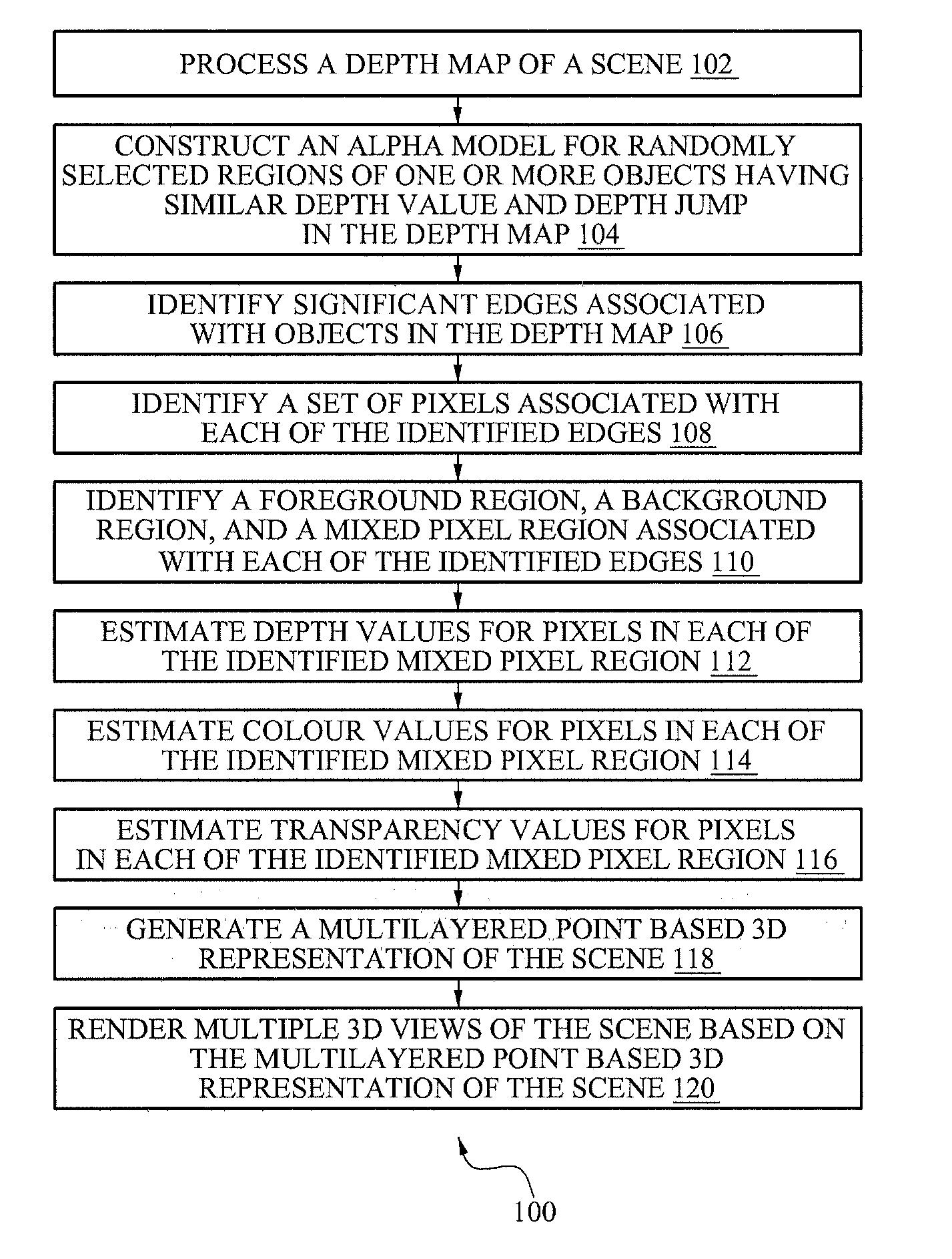
[0018]FIG. 1 illustrates a process flow chart of an exemplary method of generating a multilayered point based 3D representation of a scene, according to one embodiment. At step 102, a depth map of...


PUM


Abstract

The present invention provides a method and system of generating multilayered point based 3D representation of a scene. The method includes constructing an alpha model of randomly selected regions associated with objects with similar depth value and depth jump in a depth map of a scene, and identifying mixed pixel regions associated with edges of the objects. The method further includes estimating colour, depth and transparency values for pixels in each identified mixed pixel region using associated colour information from an image map of the scene, associated depth value information from the depth map, and transparency information from the alpha model based on the associated depth information. The method includes generating a multi-layered point based 3D representation of the scene by organising the estimated colour, transparency, and depth values. Moreover, the method includes rendering 3D views of the scene using the multi-layered point based 3D representation of the scene.

Description

TECHNICAL FIELD [0001]The present invention relates to the field of image-based rendering system, and more particularly relates to rendering three dimensional views of a scene.BACKGROUND ART [0002]Image-based rendering generates a resultant image from a random viewpoint based on three-dimensional space data of an original certain standard viewpoint (or camera). In such image-based rendering, since a real image can be input, a derivable resultant image may be generated that looks like the same real image but from a different viewpoint. One type of image rendering is a three-dimensional depth image-based rendering method, where a resultant image is rendered by using original image information and spatial depth values measured from a depth map for points and / or pixels within the original image.[0003]Such image-based rendering technique relies on one-to-one match between pixels within the original image and the depth map. In reality, points at edges of objects map to the same pixel. Des...

Claims


Application Information

Patent Timeline
Patent Type & Authority Applications(United States)
IPC IPC(8): G06T15/04
CPCG06T15/20
Inventor KANNAN, HARIPRASADIYER, KIRAN NANJUNDAMAITI, KAUSIKPURBIYA, DEVENDRABOPARDIKAR, AJIT SHYAMSUNDER
Owner SAMSUNG ELECTRONICS CO LTD
Learn More