Replaceable staple cartridge

a staple cartridge and replacement technology, applied in the field of surgical staplers, can solve the problems that the configuration of the loading unit does not permit reloading or replacing of staple cartridges

Active Publication Date: 2012-11-15
TYCO HEALTHCARE GRP LP
View PDF14 Cites 542 Cited by
  • Summary
  • Abstract
  • Description
  • Claims
  • Application Information

AI Technical Summary

Benefits of technology

[0009]Also provided is a replaceable cartridge assembly. The cartridge assembly includes a staple cartridge and a carrier configured to receive the staple cartridge. The carrier includes a proximal end configured for selective engagement with a stapling assembly. The carrier may have a resilient spring arranged to form a connection with a stapling as

Problems solved by technology

The configuration of the loading units does not permit reloading or re

Method used


Image

  • Replaceable staple cartridge
  • Replaceable staple cartridge
  • Replaceable staple cartridge

Examples


Embodiment Construction

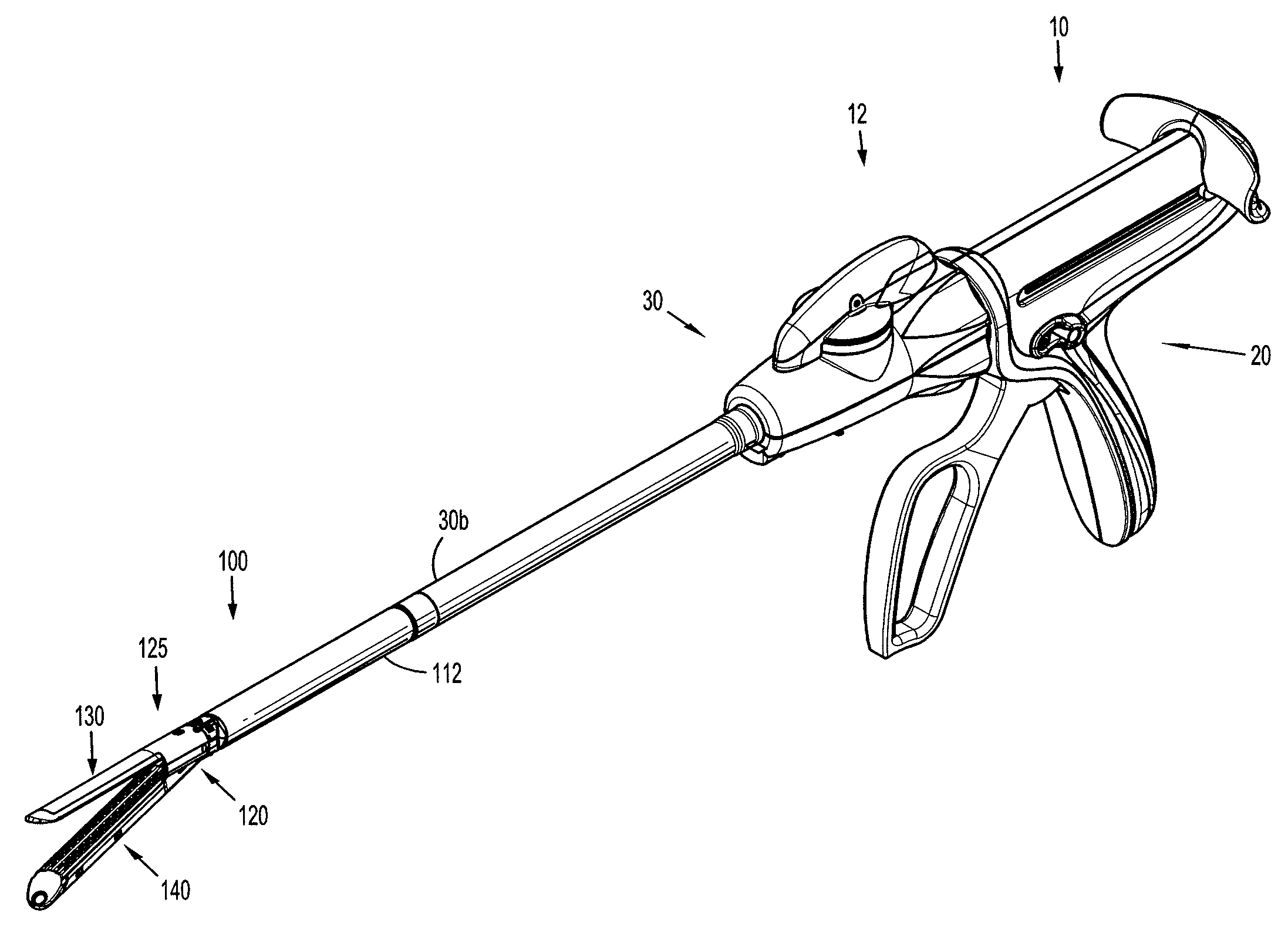
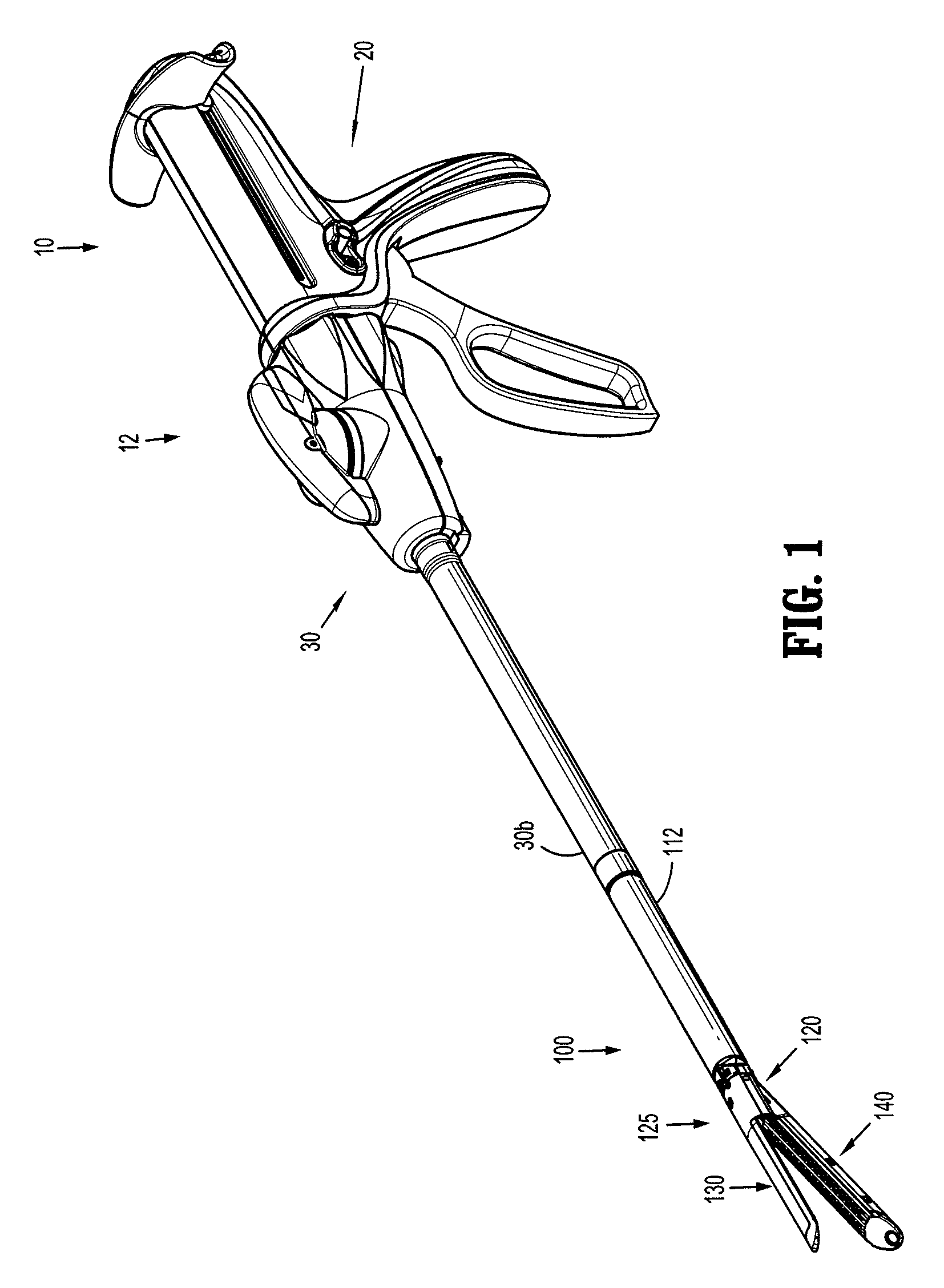
[0041]Embodiments of the presently disclosed loading unit with a replaceable staple cartridge will now be described in detail with reference to the drawings wherein like numerals designate identical or corresponding elements in each of the several views. As is common in the art, the term “proximal” refers to that part or component that is closer to the user or operator, i.e. surgeon or physician, while the term “distal” refers to that part or component that is further away from the user. Although the replaceable staple cartridges of the present disclosure will be described as relates to a disposable loading unit for use with a surgical stapler, the presently disclosed replaceable cartridge assembly may be modified for use with surgical stapling devices that do not include a disposable loading unit.

[0042]FIG. 1 illustrates a surgical stapling device 10 including an embodiment of a disposable loading unit according to the present disclosure shown generally as loading unit 100. As show...


PUM

PropertyMeasurementUnit
Flexibilityaaaaaaaaaa

Abstract

A stapling device including a replaceable loading unit is provided. The loading unit includes an elongated body and a stapling assembly having a first jaw and a second jaw. The first jaw of the stapling assembly includes an anvil assembly. The second jaw of the stapling assembly includes a releasably mounted cartridge assembly having a detent connection with the stapling assembly. Also provided is a tool for removing facilitating the separation of a replaceable cartridge assembly from a loading unit.

Description

BACKGROUND[0001]1. Technical Field[0002]The present disclosure relates to surgical staplers. More particularly, the present disclosure relates to a surgical stapler including a replaceable staple cartridge assembly.[0003]2. Background of Related Art[0004]Surgical devices for first grasping or clamping tissue between opposing jaw structure and then stapling the tissue with surgical fasteners are well known in the art. In some instruments a knife is provided to cut the tissue which has been stapled by the fasteners. Instruments for this purpose typically include two elongated members, one of which carries a staple cartridge and the other of which includes an anvil. The staple cartridge houses a plurality of staples arranged in at least two lateral rows. The anvil defines a surface for forming the staple legs as the staples are driven from the staple cartridge. Generally, the stapling operation is effected by cam bars that travel longitudinally through the staple cartridge. A knife may...

Claims


Application Information

Patent Timeline
IPC IPC(8): A61B17/068B25B27/14B65D85/24
CPCA61B17/00234A61B17/07207A61B19/026Y10T29/53909A61B2017/00477A61B2017/07271A61B2017/2931A61B2017/00473A61B50/30A61B2090/0814
Inventor KOSTRZEWSKI, STANISLAW
Owner TYCO HEALTHCARE GRP LP
Why Eureka
Try Eureka