
Force amplifying driver system and jetting dispenser and method of dispensing fluid

a driver system and driver technology, applied in the field of driver systems, can solve the problems of compromising affecting the performance of the device, and affecting so as to reduce the overall length of the actuated device or the driven member. the effect of reducing the overall length of the actuated devi

Active Publication Date: 2012-11-15
NORDSON CORP
View PDF4 Cites 12 Cited by
  • Summary
  • Abstract
  • Description
  • Claims
  • Application Information

AI Technical Summary

Benefits of technology

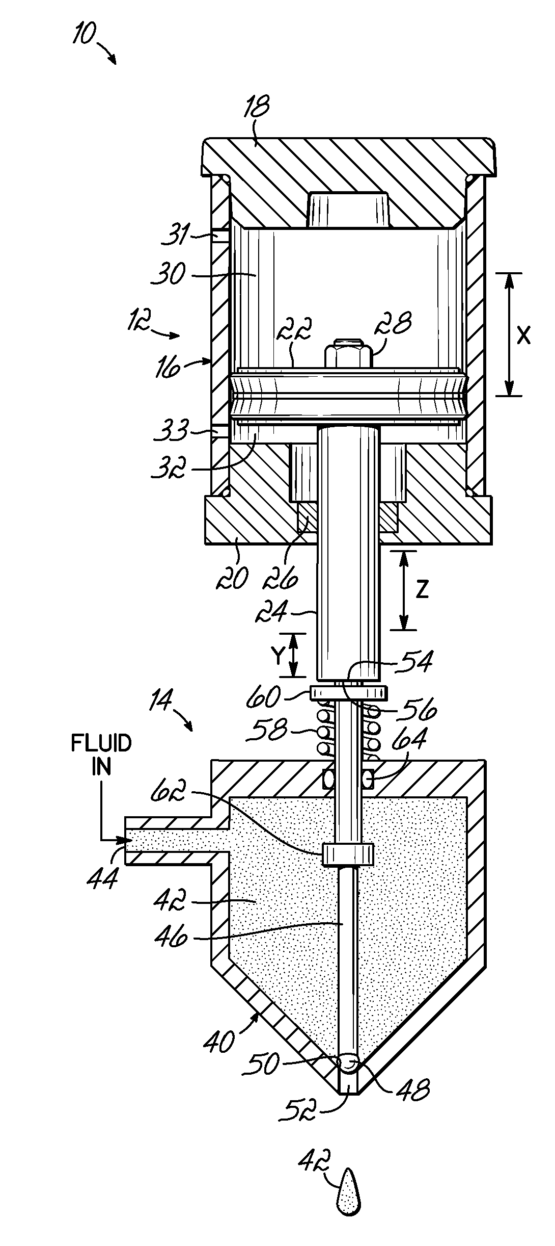
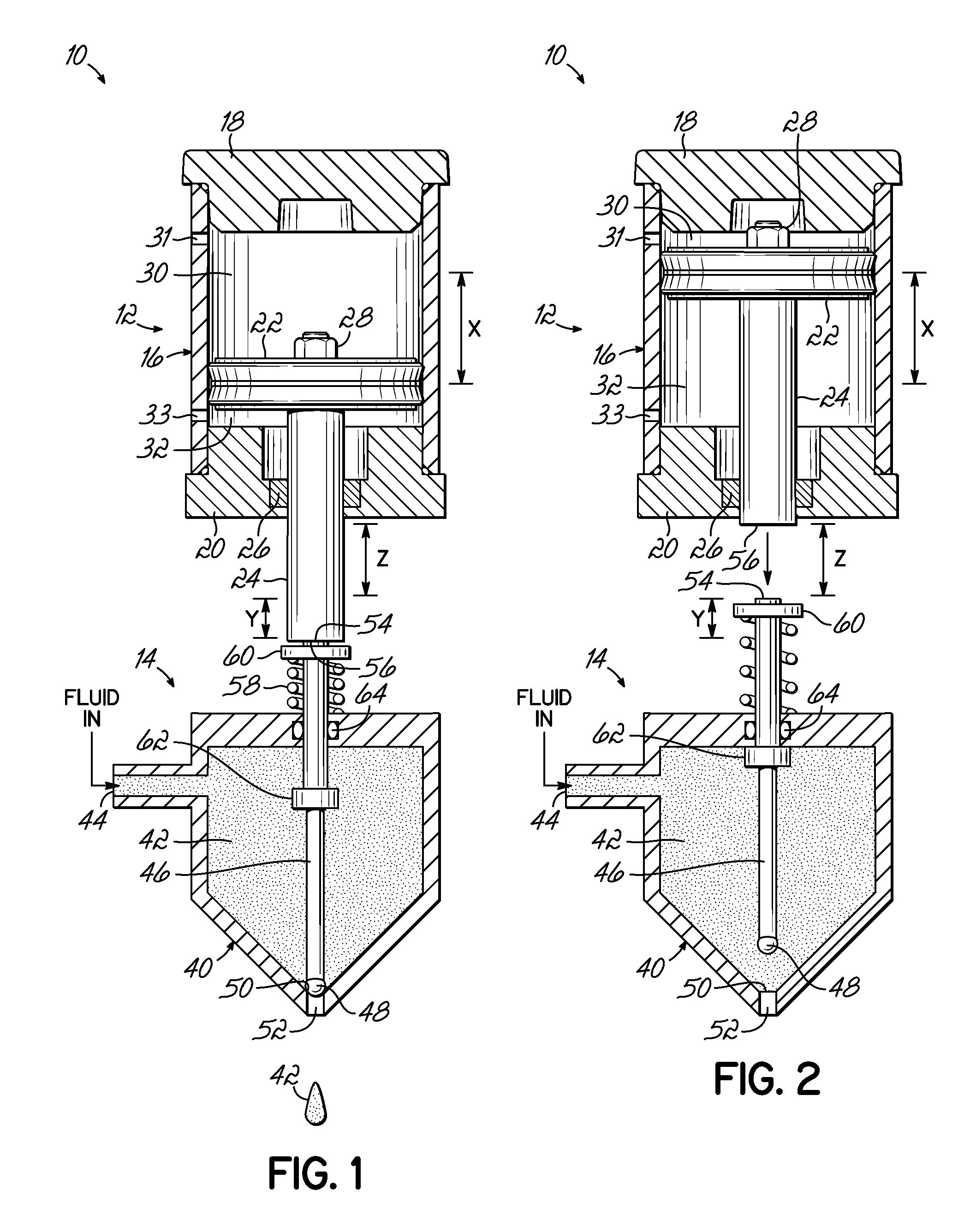
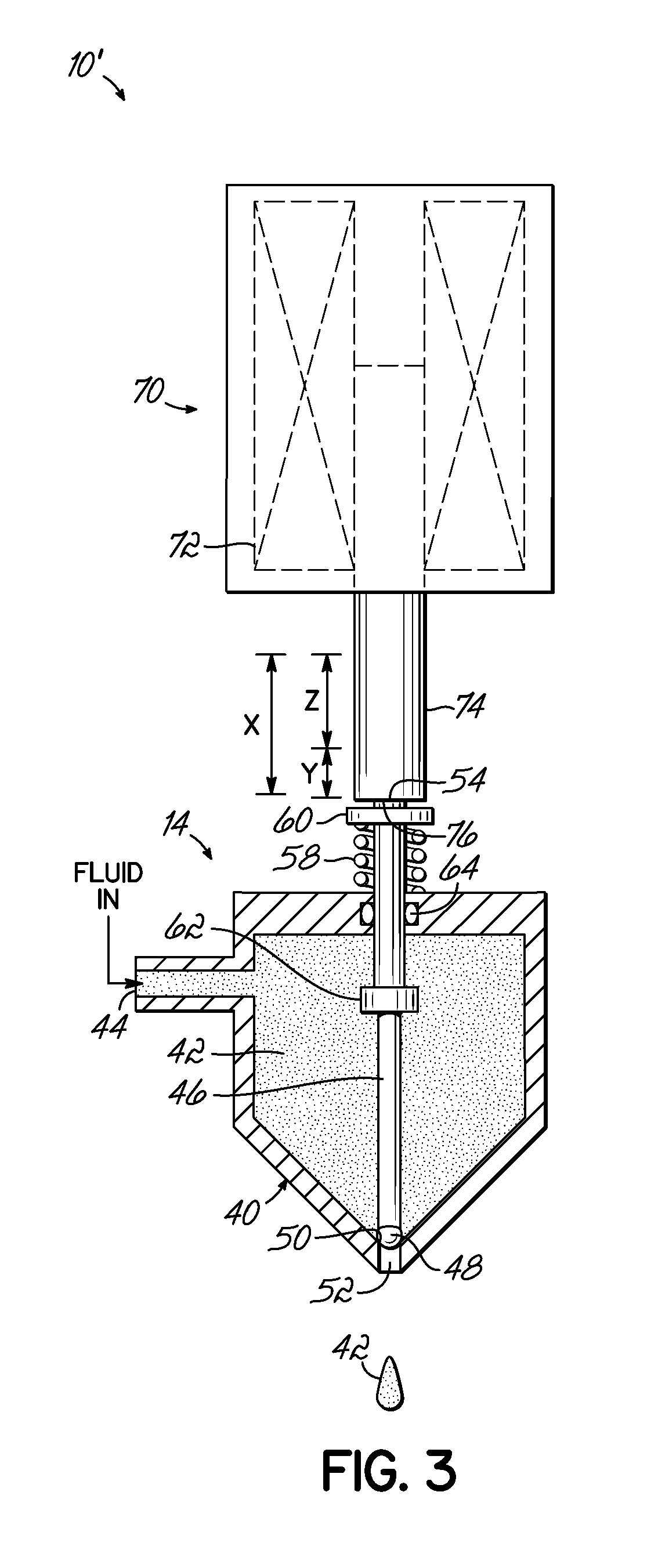
[0005]The present invention generally provides a force amplifying driver system including an actuator with a powered actuating member mounted for movement along a first distance. A driven member is mounted for movement along a second distance which is less than the first distance. The powered actuating member moves through a gap before mechanically coupling with the driven member and then moves in a mechanically coupled fashion with the driven member along the second distance. In this manner, energy is transferred from the powered actuating member to the driven member along the second distance. During its travel through the gap, the powered actuating member accelerates and creates kinetic energy which is then transferred to the driven member upon mechanical coupling (e.g., contact) and during the movement along the second distance. Thus, the powered actuating member and the driven member are mechanically coupled only during a portion of the overall travel distance of the powered actuating member. The actuator thereby delivers energy to the actuated device or driven member in an amount equal to a larger actuator in a conventional directly coupled driver mechanism. In addition, separating the actuator from the driven member enables the stroke length of the driven member to be shortened and the overall length of the actuated device or driven member to be reduced.

Problems solved by technology

If the actuator is undersized, the performance of the device may be compromised.
Direct coupling of the actuator to the device performing the work may also present challenges if the actuator is sensitive to heat and the driven element is part of a heated system.

Method used


Image

  • Force amplifying driver system and jetting dispenser and method of dispensing fluid
  • Force amplifying driver system and jetting dispenser and method of dispensing fluid
  • Force amplifying driver system and jetting dispenser and method of dispensing fluid

Examples


Embodiment Construction

[0012]The following detailed description will be given in the context of a fluid jetting dispenser, schematically represented, in order to illustrate principles of the invention. However, the principles may be applied to other driver systems for performing other types of work in situations, for example, in which it is desired to quickly accelerate a driven member and in which it may be desirable to minimize the size of the actuator used to move the driven member and / or to provide other benefits.

[0013]Referring to FIGS. 1 and 2, a fluid jetting dispenser 10 is illustrated and generally includes an actuator 12 and a jetting valve portion 14. Dispenser 10 is only schematically illustrated, but may include any desired design features such as any of those illustrated and / or discussed in the above-incorporated patents or publication. As mentioned, actuator 12 may comprise any numerous types of pneumatic or electric powered actuators, for example, but for illustration purposes actuator 12 ...


PUM


Abstract

A force amplifying driver system including an actuator (12) with a powered actuating member (22) mounted for movement along a first distance “X”. A driven member (46) mounted for movement along a second distance or working distance “Y” which is less than the first distance “X”. The powered actuating member (24) is movable through a gap “Z” before being mechanically coupled with the driven member (46) and subsequently moves with the driven member (46) along the second distance “Y”. Energy is transferred from the powered actuating member (24) to the driven member (46) along the second or working distance “Y”. The force amplifying driver system may be used for actuating a fluid jetting dispenser (14).

Description

CROSS-REFERENCE TO RELATED APPLICATION[0001]This application claims the priority of U.S. Provisional Patent Application Ser. No. 61 / 267,583, filed on Dec. 8, 2009 (pending), the disclosure of which is incorporated by reference herein.TECHNICAL FIELD[0002]Generally, the invention relates to driver systems for moving a driven element with quick, short acceleration, and more specifically, to jetting dispenser or valve in which a valve member is quickly accelerated to dispense or jet material onto a substrate.BACKGROUND[0003]Drivers for performing various work may be powered in any number of manners, such as pneumatic, hydraulic, electric, magnetic, or combinations thereof. Oftentimes, the drivers for dispensing liquids, such as hot melt materials, comprise pneumatic actuators or electro-magnetic solenoids.[0004]Various types of jetting dispensers are known such as shown in U.S. Pat. Nos. 5,320,250; 5,747,102; and 6,253,957; and U.S. Publication No. 2006 / 0157517, the disclosures of whic...

Claims


Application Information

Patent Timeline
Patent Type & Authority Applications(United States)
IPC IPC(8): B05B1/30
CPCB05B1/3053B05C5/0291B05C5/0225B05B1/306B05C5/0237
Inventor SAIDMAN, LAURENCE B.TAYLOR, EDWARD C.
Owner NORDSON CORP
Learn More