Transaction indentifier expansion circuitry and method of operation of such circuitry

Active Publication Date: 2012-11-15
ARM LTD
View PDF6 Cites 33 Cited by
  • Summary
  • Abstract
  • Description
  • Claims
  • Application Information

AI Technical Summary

Benefits of technology

[0028]As mentioned previously, through use of the above described embodiments, there is no need to modify the behaviour of the master device. Hence, whilst the master device may be arranged to use different initial transaction identifiers for certain transactions, the technique of the present invention works equally well when the master device is arranged to provide the same initial transaction identifier for all transactions.
[0029]There are a number of ways in which the transaction identifier expansion circuitry can be arranged to re-order the response transfers prior to provision of those response transfers to the master device. In one embodiment, the buffer circuitry comprises a plurality of response queues, each response queue being associated with one of said revised transaction identifiers and being arranged to buffer each response transfer received from the interconnect circuitry with that associated revised transaction identifier. The reordering circuitry further comprises an identifier queue to record which revised transaction identifier has been associated with each pending transaction, and is configured to reference the identifier queue in order to determine the order in which the response transfers should be output to said master device from the plurality of response queues. Such an approach provides a particularly simple and effective technique for re-ordering the response transfers, and works particularly well when the number of revised transaction identifiers is relatively small. However, if a large number of revised transaction identifiers are provided (for example because there

Problems solved by technology

However, whilst the ability to reorder transactions can improve performance, it can give rise to a potential cyclic dependency deadlock occurring within the interconnect circuitry, for example where multiple transactions with the same transaction identifier are issued to different slave devices.
The possibilities for deadlock become more likely when multiple of the slave devices have the capability to reorder transactions.
When deadlock occurs, it is often very difficult to restore the interconnect circuitry to a normal operating state.
Therefore, when deadlock occurs it is generally required that the configuration of the interconnect be reset, which will also typically impact the operation of devices coupled thereto.
Whilst all of these techniques are effective at reducing or removing the risk of deadlock occurring, they all place significant constraints on how each master device can behave.
Again, this scheme restricts the flexibility of the master devices when issuing transactions, since certain address transfers will be prevented from being propagated if the prediction circuitry predicts that a deadlock may arise.
Further, such a scheme is relatively complex in that it requires the provision of such prediction circuitry.
However, such an approach

Method used


Image

  • Transaction indentifier expansion circuitry and method of operation of such circuitry
  • Transaction indentifier expansion circuitry and method of operation of such circuitry
  • Transaction indentifier expansion circuitry and method of operation of such circuitry

Examples


Example

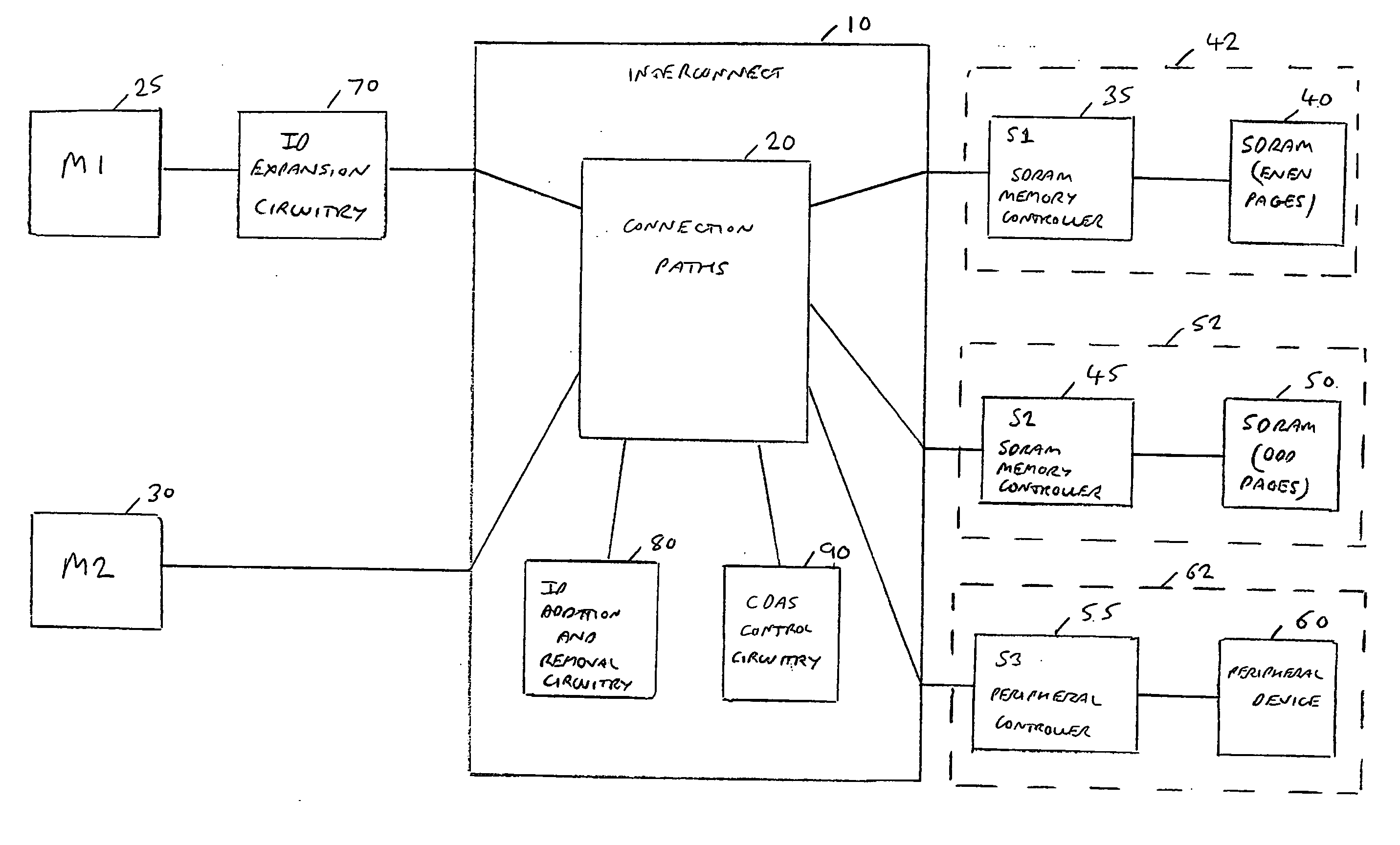
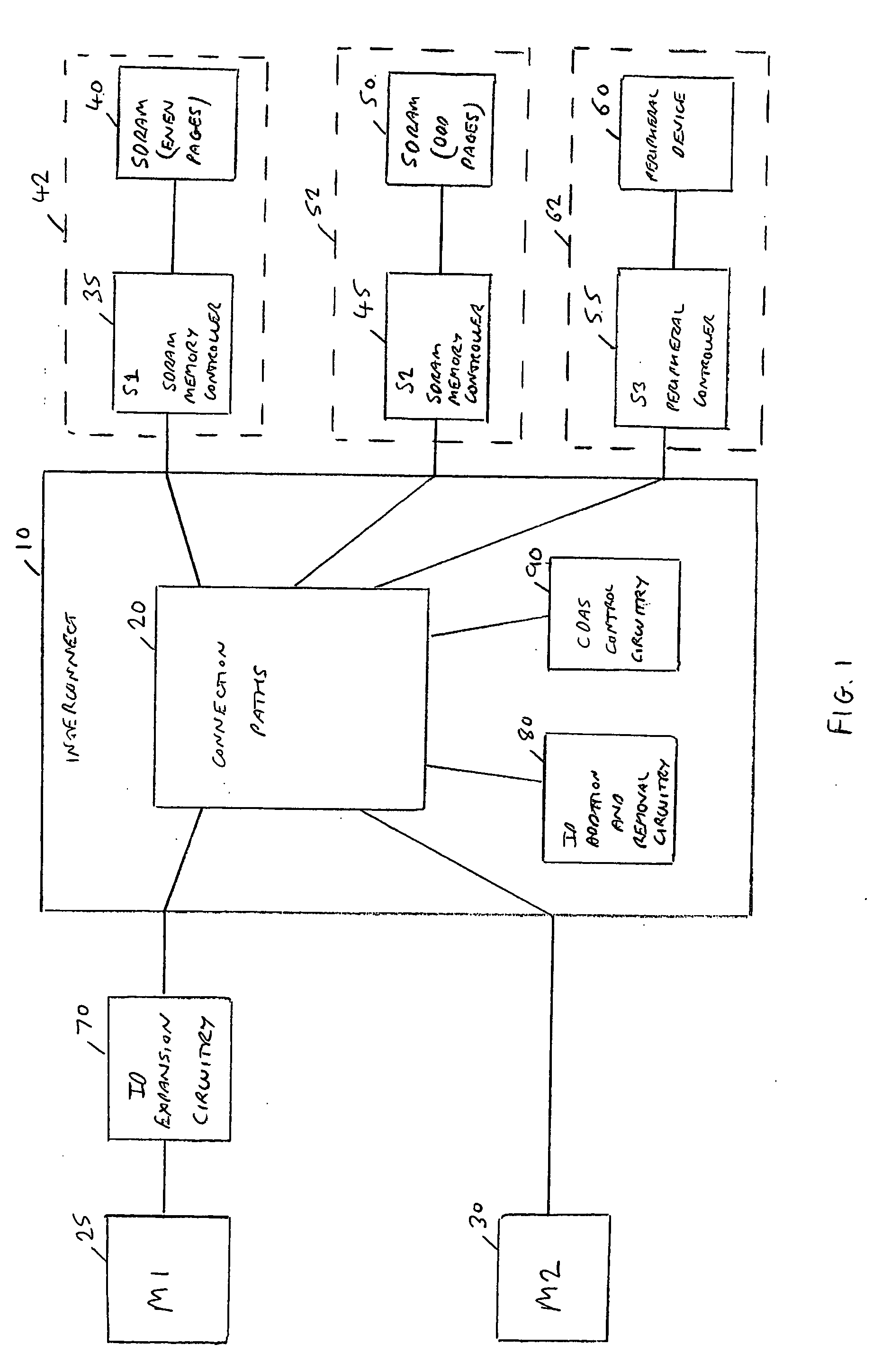
[0046]In the embodiments described below, the interconnect circuitry of a data processing apparatus employs a split transaction protocol in which separate address channels and data channels are provided, and the timing of data transfers is decoupled with respect to the timing of address transfers of a particular transaction. In one particular embodiment, the interconnect circuitry operates in accordance with the AXI protocol, and the connection paths of the interconnect circuitry provide five channels, namely a read address channel, a write address channel, a read data channel, a write data channel and a write response channel.

[0047]FIG. 1 is a block diagram of a data processing apparatus incorporating such interconnect circuitry. As shown in FIG. 1, the interconnect circuitry 10 has a number of master devices connected thereto, in this example two master devices M125 and M230, and also has a number of slave devices connected thereto, in this example the slave devices generally repr...


PUM


Abstract

Transaction identifier expansion circuitry is provided, along with a method of operating such circuitry. The transaction identifier expansion circuitry interfaces between a master device and interconnect circuitry used to couple the master device with a plurality of slave devices to enable transactions to be performed. Transaction analysis circuitry is responsive to each transaction in a sequence of transactions initiated by the master device, to compare at least one attribute of the transaction with predetermined attributes indicative of the target slave device for that transaction. Based on the comparison, an initial transaction identifier is then mapped to one of a plurality of revised transaction identifiers, such that the revised transaction identifier is dependent on the target slave device. Reordering circuitry is then arranged to buffer response transfers received from the interconnect circuitry destined for the master device, with each response transfer having the revised transaction identifier associated therewith. The reordering circuitry then re-orders the response transfers having regard to the original transaction order of those transactions within the sequence of transactions that had the same initial transaction identifier, prior to provision of each response transfer to the master device. By such an approach, the performance of a high performance master device can be maintained, by ensuring that for at least the transactions targeted to a particular subset of the slave devices, no intervention by deadlock avoidance circuitry within the interconnect is required when routing transactions to those slave devices, due to the use of different transaction identifiers when accessing those slave devices.

Description

FIELD OF THE INVENTION[0001]The present invention relates to the handling of transactions between master and slave devices coupled via interconnect circuitry.DESCRIPTION OF THE PRIOR ART[0002]Within a data processing apparatus having a plurality of master devices and slave devices, it is known to provide interconnect circuitry for coupling the master devices and the slave devices to enable transactions to be performed. Each transaction consists of an address transfer from a master device to a slave device, and one or more data transfers between that master device and that slave device. For a write transaction these data transfers will pass from the master device to the slave device (in some implementations there will additionally be a write response transfer from the slave device to the master device), whilst for a read transaction these data transfers will pass from the slave device to the master device. Any transfers from a slave device to a master device are referred to herein as...

Claims


Application Information

Patent Timeline
IPC IPC(8): G06F13/00
CPCG06F13/4022G06F13/00G06F13/1626
Inventor LIM, SEOW CHUAN
Owner ARM LTD
Why Eureka
Try Eureka