

Current mirror circuit with temperature resistance
A current mirror and circuit technology, applied in the direction of adjusting electrical variables, control/regulating systems, instruments, etc., can solve problems such as difficulty in using current mirrors, and achieve the effects of good work, reduced voltage drop, and good performance
- Summary
- Abstract
- Description
- Claims
- Application Information
AI Technical Summary
Problems solved by technology
Method used
Image

Examples
Embodiment 1
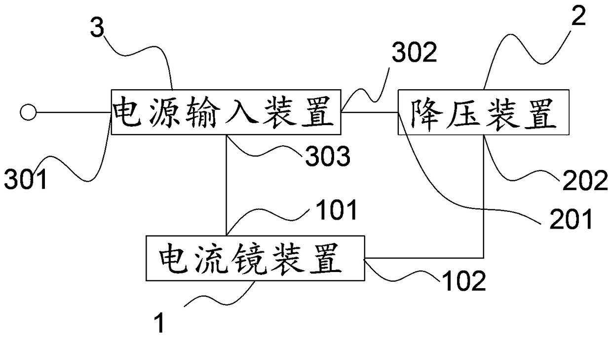
[0031] Such as Figure 1-Figure 2 As shown, a current mirror circuit with temperature resistance includes a current mirror device 1, a step-down device 2 and a power input device 3;
[0032] The power input device 3 is connected to a power supply voltage to obtain a high potential;
[0033] The step-down device 2 is connected to the power input device 3 and the current mirror device 1 respectively;
[0034] The power input terminal 301 of the power input device 3 is connected to a power supply voltage to obtain a high potential;
[0035] The step-down input terminal 201 of the step-down device 2 is connected to the first output terminal 302 of the power supply input device 3;
[0036] The current mirror input terminal 101 of the current mirror device 1 is connected to the second output terminal 303 of the power supply input device 3, and the current mirror input terminal 101 of the current mirror device 1 is connected to the step-down device 2. Output terminal 202 , the cur...
Embodiment 2
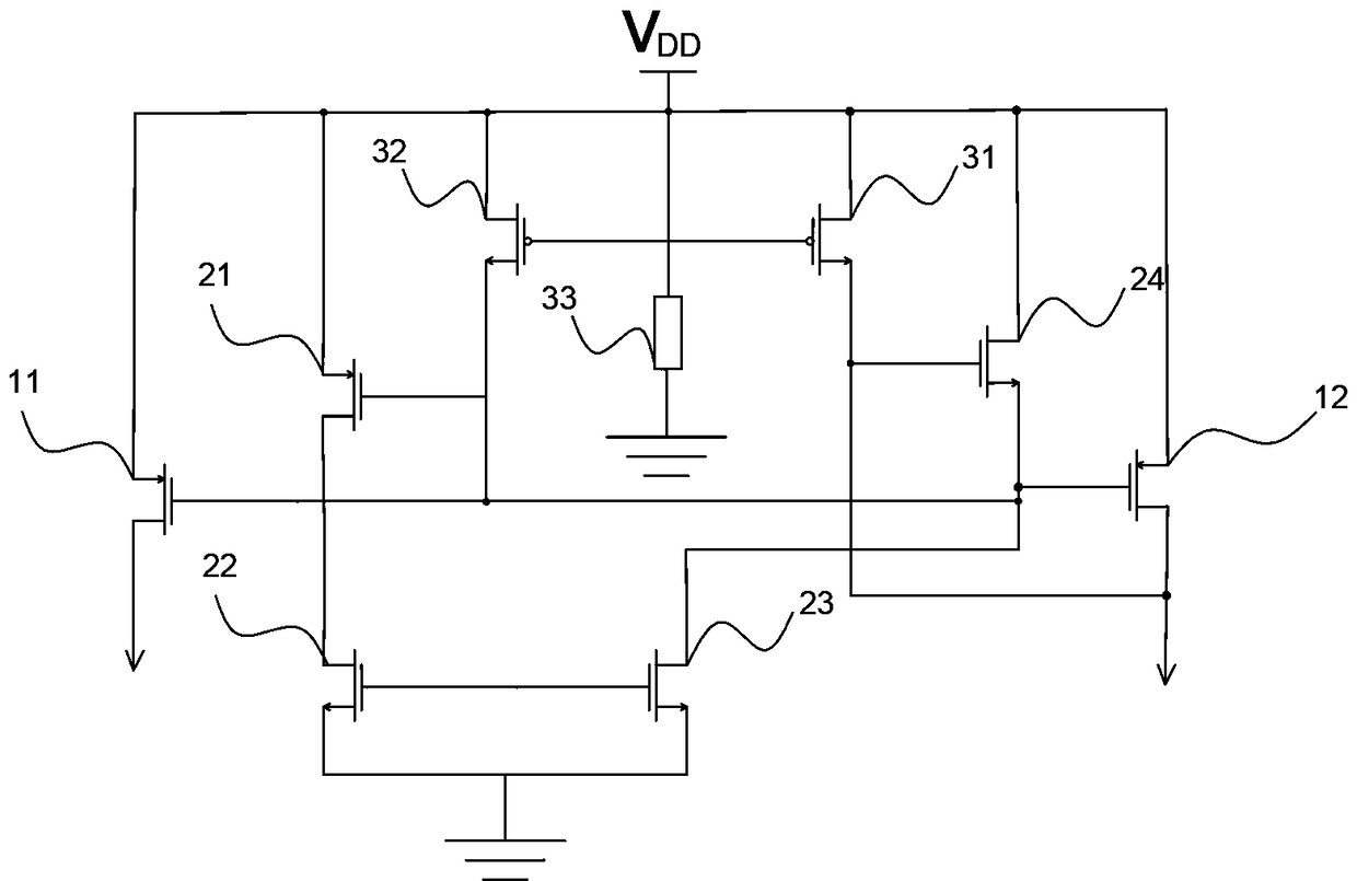
[0050] Such as figure 1 and image 3 As mentioned above, based on Embodiment 1, the difference from Embodiment 1 is that the power input device includes a seventh transistor 31, an eighth transistor 32 and a feedback network 33;
[0051] The drain of the seventh type transistor and the drain of the eighth transistor 32 are connected to the power supply voltage, the source of the seventh type transistor is connected to the gate of the sixth transistor 24, the The drain of the seventh transistor 31 is connected to the drain of the second transistor 11;
[0052] The source of the eighth transistor 32 is connected to the gate of the third transistor 21; one end of the feedback network 33 is connected to the power supply voltage, and the other end is grounded.
[0053] The seventh transistor 31 has a first temperature coefficient, which is generally negative because the seventh transistor 31 is an NMOS transistor. When the temperature changes, the seventh transistor 31 can apply a...
PUM
 Abstract
Description
Claims
Application Information