Device housing a battery and charging pad

a technology for charging pads and devices, applied in electrical apparatus construction details, safety/protection circuits, transportation and packaging, etc., to achieve the effects of reducing the on-resistance of rectifying circuit elements, reducing voltage drop, and less heat generation

Inactive Publication Date: 2011-06-02
SANYO ELECTRIC CO LTD
View PDF16 Cites 42 Cited by
  • Summary
  • Abstract
  • Description
  • Claims
  • Application Information

AI Technical Summary

Benefits of technology

[0010]In the device housing a battery described above, circuit elements with a low voltage rating are used as the rectifying circuit elements in the rectifying circuit that rectifies AC power induced in the induction coil. This reduces rectifying circuit element ON-resistance resulting in reduced voltage drop and less heat generation. Further, when a charging abnormality occurs, the induction coil is short circuited by the shorting circuit to cut-off the supply of power from the induction coil to the rectifying circuit. Consequently, this achieves the characteristic that high-voltage damage to the rectifying circuit elements used in the rectifying circuit can be effectively prevented. Specifically, the system has the characteristic that rectifying circuit element damage due to abnormally high-voltage can be reliably prevented while reducing heat generation in the device housing a battery.
[0011]The device housing a battery and charging pad of the present invention can employ a synchronous rectifying circuit 53X as the rectifying circuit 53. In this device housing a battery, since the rectifying circuit is a synchronous rectifying circuit using semiconductor switching devices such as FETs, rectifying circuit element ON-resistance can be further reduced to lower heat generation even more.
[0012]The device housing a battery and charging pad of the present invention can have a synchronous rectifying circuit 53X provided with a FET bridge circuit 60, and FETs in the FET bridge circuit 60 can serve a dual purpose as the shorting circuit 76. In this device housing a battery, when abnormal charging conditions occur, FETs in the FET bridge circuit of the synchronous rectifying circuit serve as the shorting circuit to cut-off power supplied from the induction coil. Therefore, provision of a special-purpose shorting circuit is unnecessary, circuit structure is simplified, and manufacturing cost can be reduced.
[0013]In the device housing a battery and charging pad of the present invention, the shorting circuit 56, 76 can short circuit the induction coil 51 terminals through a series capacitor 55. In this device housing a battery, since the shorting circuit short circuits the output-side of the induction coil through a series capacitor, induction coil heat generation can be effectively prevented when the shorting circuit is in the enabled short circuit state.

Problems solved by technology

Further, when a charging abnormality occurs, the induction coil is short circuited by the shorting circuit to cut-off the supply of power from the induction coil to the rectifying circuit.

Method used


Image

  • Device housing a battery and charging pad
  • Device housing a battery and charging pad
  • Device housing a battery and charging pad

Examples


Embodiment Construction

)

[0029]The following describes embodiments of the present invention based on the figures. However, the following embodiments are merely specific examples of a device housing a battery and charging pad representative of the technology associated with the present invention, and the device housing a battery and charging pad of the present invention is not limited to the embodiments described below. Further, elements indicated in the appended claims are in no way limited to the elements indicated in the embodiments.

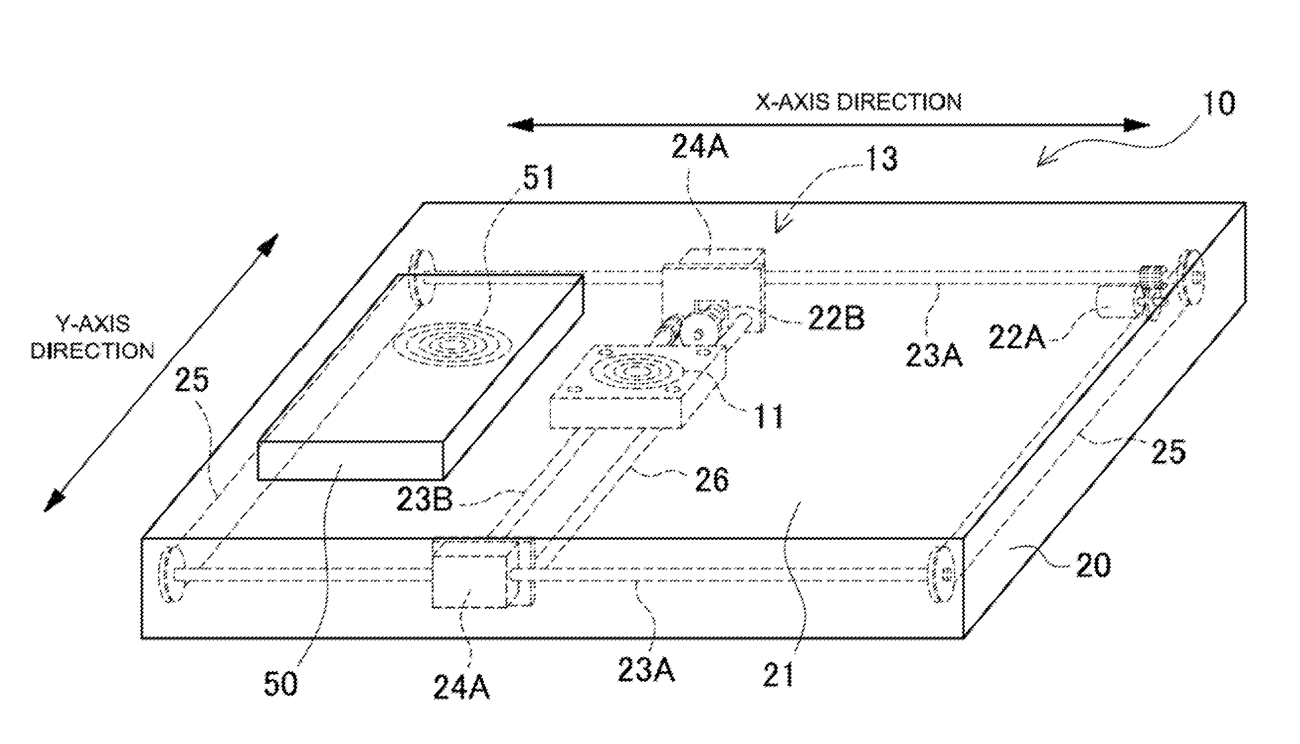
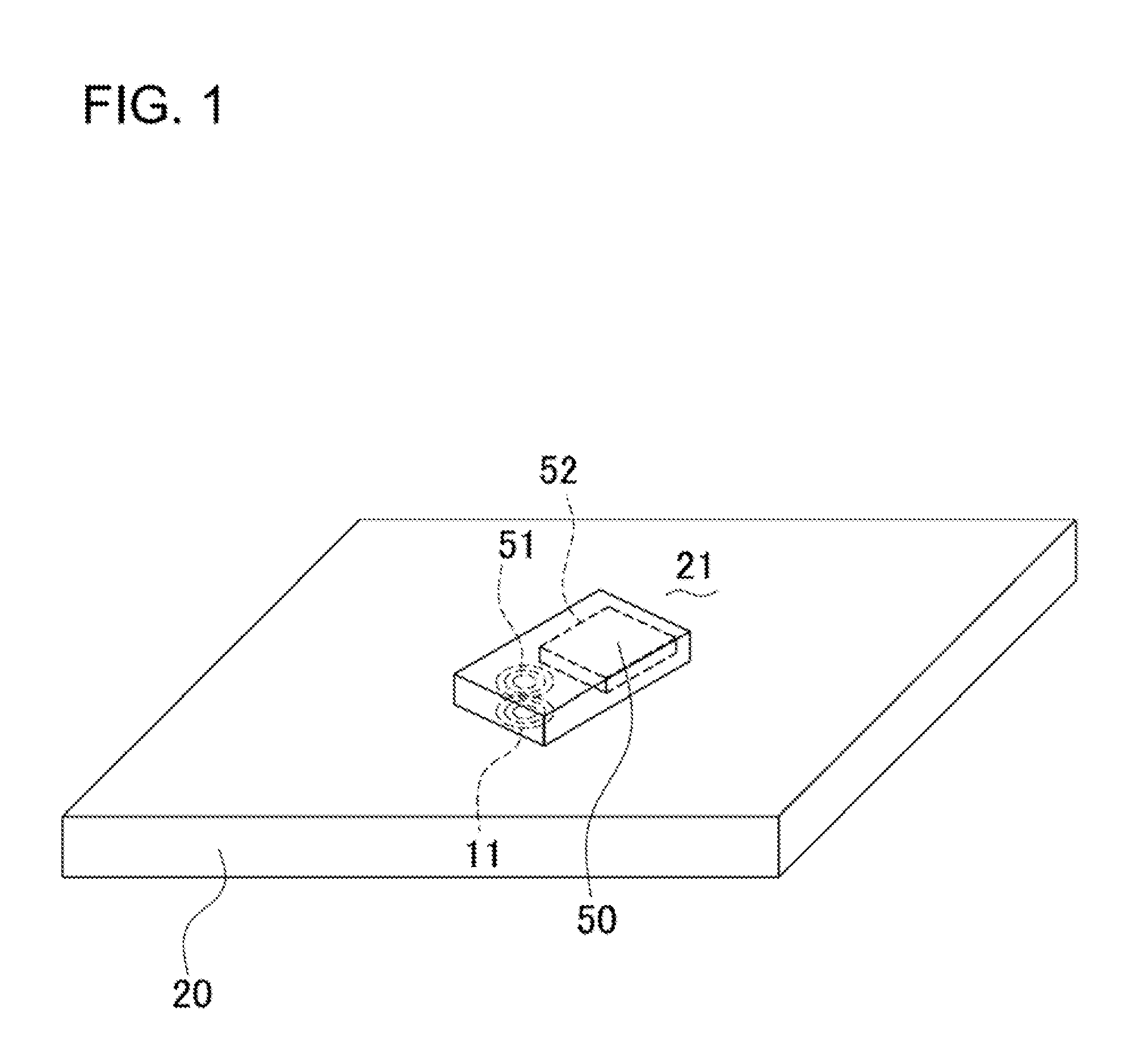
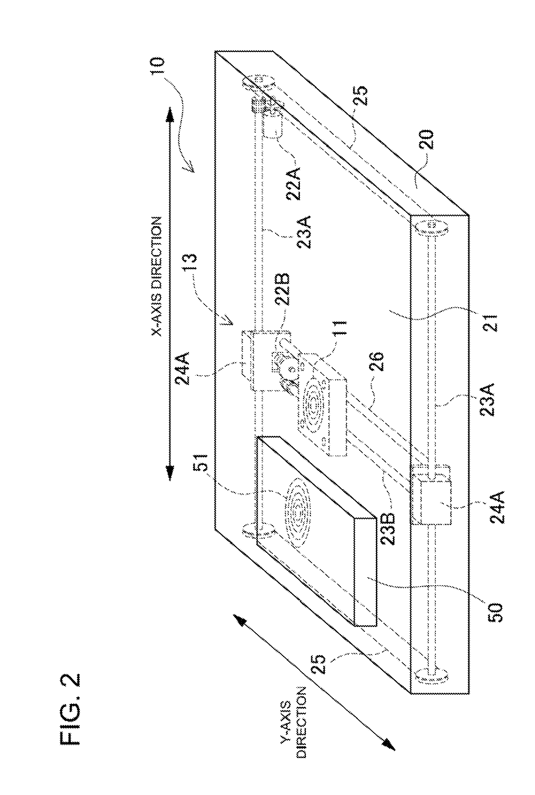
[0030]FIGS. 1-7 show structural overviews and operating principle diagrams of the charging pad 10. As shown in FIGS. 1, 2, and 7, a device housing a battery 50 is placed on top of the charging pad 10 to charge the internally housed battery 52 via magnetic induction. The device housing a battery 50 contains an induction coil 51 that magnetically couples with the power supply coil 11. The internally housed battery 50 is charged by power induced in the induction coil 51.

[0031]FI...


PUM


Abstract

A charging pad 10 is provided with a power supply coil 11, and a device housing a battery 50 containing an induction coil 51. A device housing a battery 50 is provided with a rectifying circuit 53 that rectifies AC power induced in the induction coil 51, a charging circuit 54 that charges the internal battery 52 with output from the rectifying circuit 53, a shorting circuit 56 that short circuits the terminals of the induction coil 51, and a control circuit 57 that controls the shorting circuit 56 ON when a charging abnormality is detected. If the control circuit 57 detects a charging abnormality during power transmission from the charging pad 10 power supply coil 11 to the device housing a battery 50 induction coil 51, it controls the shorting circuit 56 ON to cut-off the supply of power from the induction coil 51 to the rectifying circuit 53.

Description

BACKGROUND OF THE INVENTION[0001]1. Field of the Invention[0002]The present invention relates to a device housing a battery (or batteries) such as a battery pack or mobile telephone, and to a charging pad that transmits power by magnetic induction to the device housing a battery to charge the battery inside.[0003]2. Description of the Related Art[0004]A charging pad (charging stand, charging cradle) has been developed to charge an internally housed battery by transmitting power from a power supply coil (transmitting coil, primary coil) to an induction coil (receiving coil, secondary coil) by magnetic induction (refer to Japanese Laid-Open Patent Publication H09-63655 [1997]).[0005]JP H09-63655A cites a configuration with a charging pad housing a power supply coil driven by an alternating current (AC) power source, and a battery pack containing an induction coil that magnetically couples with the power supply coil. The battery pack houses circuitry to rectify AC power induced in the ...

Claims


Application Information

Patent Timeline
Patent Type & Authority Applications(United States)
IPC IPC(8): H05K7/02H02J7/00
CPCH02J7/025H02J7/00302H02J7/0044H02J50/80H02J50/60H02J50/90H02J50/12H02J50/40
Inventor TERAO, KYOZOTOYA, SHOICHI
Owner SANYO ELECTRIC CO LTD
Why Eureka
Try Eureka