Car power source apparatus

a power source and car technology, applied in the direction of battery/fuel cell control arrangement, safety/protection circuit, electric devices, etc., can solve the problems of low probability of contacts fusing together in both the contactor and pre-charge relay, abnormal cut-off of battery output, etc., to achieve extended contact life, low damage, and high capacity contacts

Inactive Publication Date: 2009-08-27
SANYO ELECTRIC CO LTD
View PDF15 Cites 44 Cited by
  • Summary
  • Abstract
  • Description
  • Claims
  • Application Information

AI Technical Summary

Benefits of technology

[0011]A car power source apparatus having the configuration described above realizes the characteristic that battery output can be reliably cut-off in abnormal circumstances while achieving long contactor lifetime. This is because the pre-charge resistor is connected in parallel with a contactor and the pre-charge relay is connected in series with that contactor. In a power source apparatus of this configuration, the contactor connected in series with the pre-charge relay is maintained OFF, and the pre-charge relay is turned ON to pre-charge the car-side capacitor. Subsequently, the pre-charge relay is maintained ON, and the contactor connected in series with the pre-charge relay is switched ON to connect the battery to the car-side. In this state, battery output is connected to the car-side via the pre-charge relay and the contactors. If a car-side short circuit occurs and contacts fuse together, as long as the contacts of both the pre-charge relay and the series connected contactor do not fuse together, battery output can be cut-off in an abnormal situation. Contact fusing for a series connection of contactor and pre-charge relay can be less likely. This is because energy resulting from short circuit current flow is distributed among, and dissipated by the contacts of the contactor and the pre-charge relay. For example, if the contacts of both the contactor and pre-charge relay are “chattering,” energy consumption is distributed between both sets of contacts and contact fusing is less likely. Even if contact fusing occurs under these conditions, the probability of contacts fusing together in both the contactor and pre-charge relay is low. Therefore, battery output can be cut-off by the contacts that do not fuse together. If one set of contacts for the contactor and pre-charge relay retain their ON state without “chattering” under short circuit current conditions while the other set of contacts “chatters,” the contacts with no “chatter” will not fuse together even if the “chattering” contacts fuse.
[0013]The contactor 2 connected in series with the pre-charge relay 7 can be provided with longer lifetime contacts than those of the pre-charge relay 7, and the pre-charge relay 7 can be provided with higher capacity contacts than those of the contactor 2 connected in series with the pre-charge relay 7. In this power source apparatus, contacts of the pre-charge relay, which are high-capacity type contacts, are difficult to fuse together with short circuit current, and battery output can be cut-off in abnormal circumstances by switching the pre-charge relay OFF. Further, since the contactor connected in series with the pre-charge relay uses long-lifetime contacts, contact lifetime for both the contactor and the pre-charge relay can be extended by switching the series connected contactor OFF prior to switching the pre-charge relay OFF. Consequently, contact lifetime can be extended while allowing reliable cut-off of battery output in abnormal circumstances.
[0014]Contacts of the contactor 2 connected in series with the pre-charge relay 7 can be long-lifetime contacts having tungsten at least on the surface. Specifically, contacts of the contactor 2 connected in series with the pre-charge relay 7 can be long-lifetime contacts with tungsten layered on a copper surface. Further, for the contactor 2 connected in series with the pre-charge relay 7, contacts on one side can be copper, and those on the other side that mate with the copper contacts can be long-lifetime contacts having a tungsten surface. Tungsten contacts can be repeatedly cycled ON and OFF with little damage allowing extended lifetime for the contactor connected in series with the pre-charge relay.
[0015]Contacts of the pre-charge relay 7 can be high-capacity type contacts made of copper. In this power source apparatus, short circuit induced fused contacts can be prevented while reducing voltage drop across the pre-charge relay. This is because the copper used in the contacts has low electrical resistance and high specific heat.
[0016]Contacts of the second contactor 2B can be higher capacity type contacts compared to those of the first contactor 2A. Further, contacts of the second contactor 2B can be copper high-capacity type contacts. In this power source apparatus, fusing together of the contacts of the second contactor due to short circuit current can be prevented, and battery output can be reliably cut-off in abnormal circumstances.

Problems solved by technology

If a car-side short circuit occurs and contacts fuse together, as long as the contacts of both the pre-charge relay and the series connected contactor do not fuse together, battery output can be cut-off in an abnormal situation.
Even if contact fusing occurs under these conditions, the probability of contacts fusing together in both the contactor and pre-charge relay is low.
In this power source apparatus, contacts of the pre-charge relay, which are high-capacity type contacts, are difficult to fuse together with short circuit current, and battery output can be cut-off in abnormal circumstances by switching the pre-charge relay OFF.

Method used


Image

  • Car power source apparatus
  • Car power source apparatus
  • Car power source apparatus

Examples


Embodiment Construction

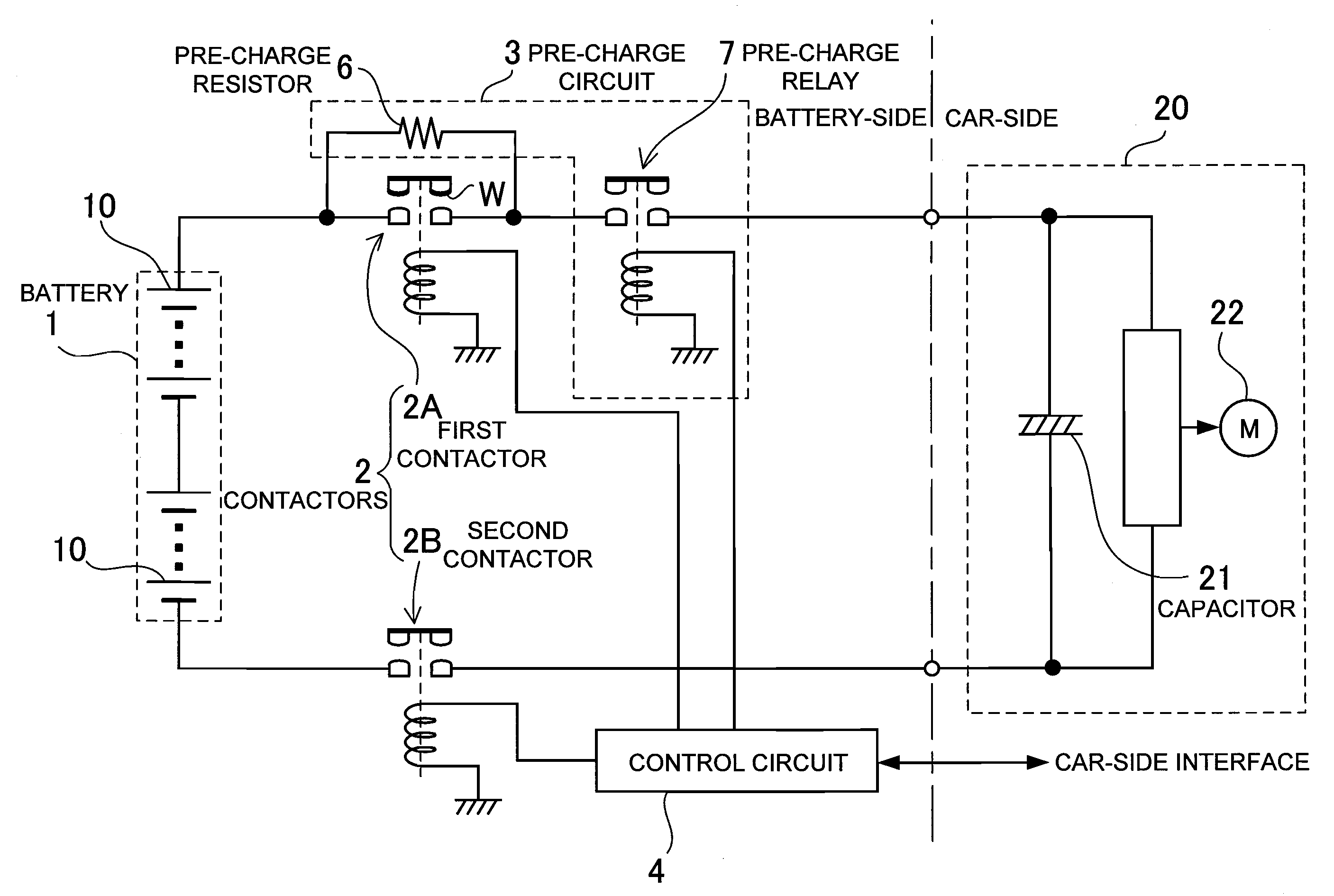
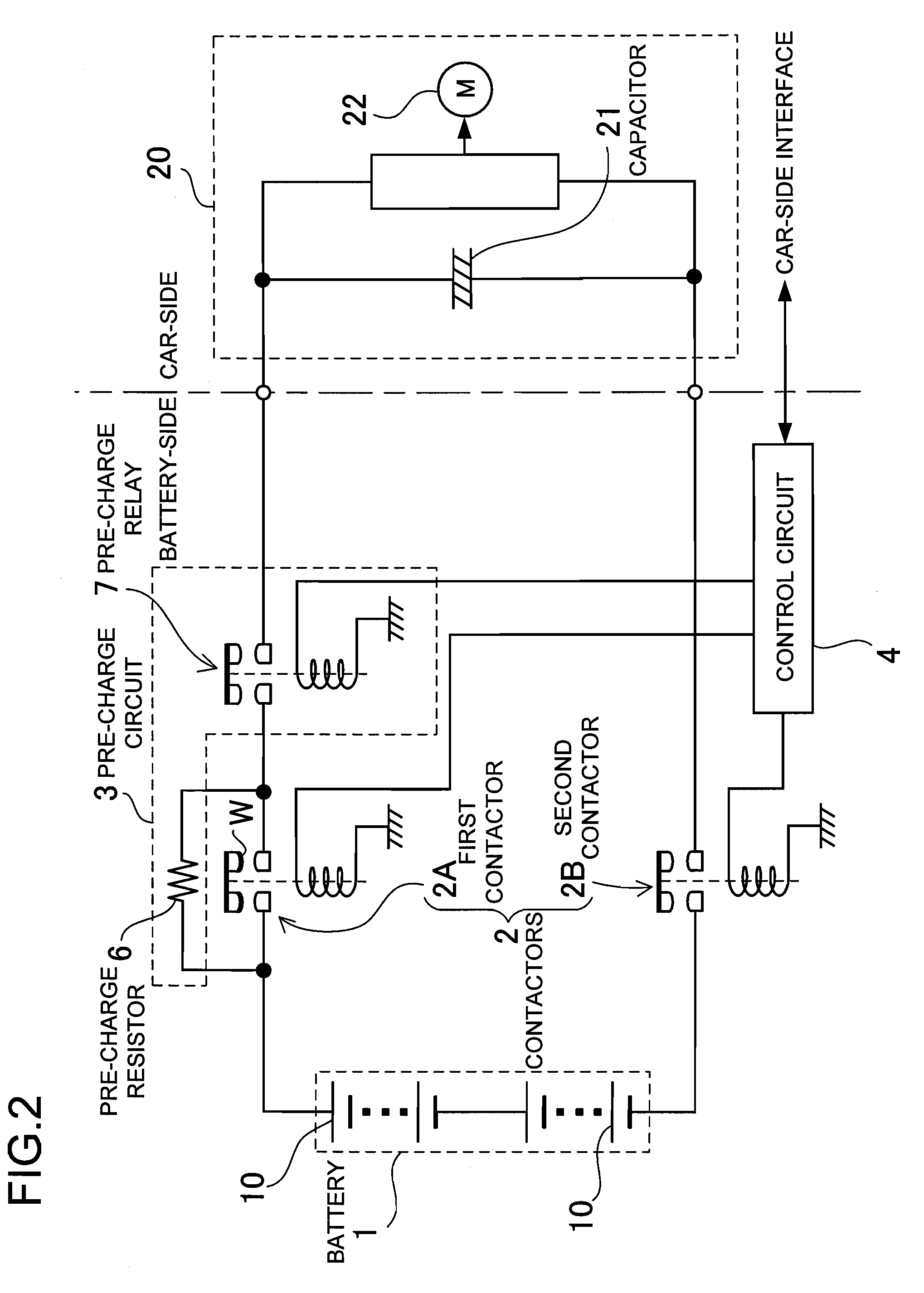
[0024]The car power source apparatus shown in FIG. 2 is installed in a hybrid car or electric automobile, and is connected to an electric motor 22 as its load 20 to drive the vehicle. The power source apparatus of the figure is provided with a driving battery 1; first and second contactors 2 connected to the output-side of the battery 1; a pre-charge circuit 3 to pre-charge the load 20 capacitor 21 prior to switching the first contactor 2A ON; and a control circuit 4 to control the pre-charge circuit 3, the first contactor 2A, and the second contactor 2B ON and OFF.

[0025]As shown in FIG. 3, the power source apparatus of the present invention can have a circuit configuration with a pre-charge circuit 3 and contactor 2 connected only at the positive-side of the battery 1, and with no contactor 2 connected at the negative-side of the battery 1. In addition, although not illustrated, a circuit configuration with a pre-charge circuit 3 and contactor 2 connected only at the negative-side ...


PUM


Abstract

The car power source apparatus is provided with contactors 2 connected to the output-side of the battery 1; a pre-charge circuit 3 made up of a series connected pre-charge resistor 6 and a pre-charge relay 7, which is connected with a contactor 2 to supply auxiliary charge to a capacitor 21 connected to the car-side of the battery 1; and a control circuit 4 to control the contactors 2 and pre-charge relay 7.The pre-charge resistor 6 is connected in parallel with a contactor 2, and the pre-charge relay 7 is connected in series with that contactor 2. The control circuit 4 switches the pre-charge relay 7 ON to pre-charge the car-side capacitor 21, and then switches the contactor 2 ON to connect the battery 1 to the car-side.

Description

BACKGROUND OF THE INVENTION[0001]1. Field of the Invention[0002]The present invention relates to a power source apparatus that connects the vehicle driving battery to the car-side load via contactors (high power, electric automotive-grade relays), and in particular relates to a car power source apparatus that prevents the detrimental effects of fused contacts.[0003]2. Description of the Related Art[0004]The car power source apparatus has first and second contactors that connect to the positive and negative output-side of the battery. In this power source apparatus, contactors are switched ON to connect the battery with the car-side load. When the vehicle is not in use, for example, when the automobile ignition switch is OFF, the contactors are switched OFF. Furthermore, if the automobile has an accident or collision, the contactors are also switched OFF to cut-off battery output and increase safety.[0005]A capacitor with a large capacitance value is connected in parallel with the ca...

Claims


Application Information

Patent Timeline
Patent Type & Authority Applications(United States)
IPC IPC(8): H02H7/18H02J7/34
CPCB60R16/03H02H3/05H02H9/001H02J7/0031B60L2270/20B60L3/0046B60L3/04B60L2240/36B60L3/003H02J2310/46B60L58/18Y02T10/70
Inventor SAKATA, HIDEKIOOSAWA, TAKESHIMATSUMOTO, AKIRA
Owner SANYO ELECTRIC CO LTD
Why Eureka
Try Eureka