Signal cutout device, optical connector and optical fiber coupler

a technology of optical connectors and cutout devices, applied in the direction of optical waveguide light guides, instruments, optics, etc., can solve the problems of inability to easily change the configuration of the ftth system, failure or its characteristics might change, inferior yield and cost, etc., to achieve convenient and inexpensive construction, easy connection, and reliable cutting

Inactive Publication Date: 2005-07-21
SHOWA ELECTRIC WIRE & CABLE CO
View PDF1 Cites 6 Cited by
  • Summary
  • Abstract
  • Description
  • Claims
  • Application Information

AI Technical Summary

Benefits of technology

[0024] According to the optical fiber coupler of the present invention, the first and second index variation sections in which the period of the grating varies gradually along the optical axis are serially provided in the core of the optical fiber, so that a signal, such as an image signal which is transmitted from an optical line terminal, can be reliably cut off. Besides, the port itself of the optical fiber coupler serves as an optical waveguide, so that the coupler can be easily connected to an optical fiber which is an optical transmission line. As a result, an FTTH system can be easily and inexpensively constructed by diverting an FTTB system which is currently in operation, and an FTTH system which does not require “delivery of an image signal” can be easily changed-over to an FTTH system which requires the “delivery of an image signal”.

Problems solved by technology

Since, however, the former optical device is used with the filter of multi-layer dielectric films inserted between optical fibers and fixed by a binder or with this filter held between connectors, it might cause a failure or its characteristics might change under the severe temperature environment.
Besides, in the latter optical device, the fiber Bragg grating which is elongate must be used for securing the isolation of at least 40 dB in the wide band of 1550-1560 nm, so that in the manufacture of such a fiber Bragg grating, a phase mask having the special specification of a chirp rate of at most 6.3 nm / cm is required, resulting in the drawbacks of an inferior yield and an increase in cost.
In such a case, the splicing work of the fiber Bragg grating needs to be redone, to incur the drawback that the configuration of the FTTH system cannot be changed-over with ease.

Method used


Image

  • Signal cutout device, optical connector and optical fiber coupler
  • Signal cutout device, optical connector and optical fiber coupler
  • Signal cutout device, optical connector and optical fiber coupler

Examples


Embodiment Construction

[0036] Now, preferred embodiments of a signal cut-off device, an optical connector and an optical fiber coupler according to the present invention will be described with reference to the drawings.

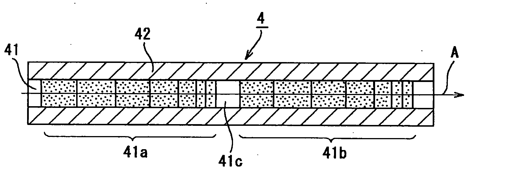
[0037]FIG. 1 shows a vertical sectional view of a signal cut-off device according to the present invention. Referring to the figure, the signal cut-off device 4 according to the present invention includes an optical fiber which has a clad 42 on the outer periphery of a core 41 that contains quartz-based glass as its main ingredient. In the core 41, first and second variation sections of a refractive index, 41a and 41b are formed serially in the longitudinal direction of this core 41, in the following way: A standard wide-band mask (not shown) whose chirp rate is 11 nm / cm is disposed outside the optical fiber, and the optical fiber is irradiated with ultraviolet radiation from outside the wide-band mask, whereby the first index variation section 41a in which the period of a grating varies g...


PUM


Abstract

A signal cut-off device 4 includes an optical fiber which has a clad 42 on the outer periphery of a core 41, and first and second variation sections of a refractive index, 41a and 41b in which the period of a grating varies gradually along an optical axis are serially formed in the longitudinal direction of the core 41.
An optical connector which is detachably connected to the predetermined place of an optical transmission line includes a housing which has a plug-styled portion at a front end part and a jack-styled portion at a rear end part, and a ferrule which is mounted in the plug-styled portion. The signal cut-off device 4 is installed in the hole of the ferrule. An optical fiber coupler includes a coupler body which multiplexes/demultiplexes an uplink signal (1260-1360 nm) and a downlink signal (1480-1580 nm), a COM port which is provided on the input side of the coupler body, and a 1.55 port and a 1.3 port which are provided on the output side of the coupler body. A second connector is mounted on the end part of an optical fiber constituting the COM port, a PD is mounted on the end part of an optical fiber constituting the 1.55 port, and an LD is mounted on the end part of an optical fiber constituting the 1.3 port.

Description

TECHNICAL FIELD [0001] The present invention relates to a signal cut-off device, an optical connector and an optical fiber coupler, and it relates to a signal cut-off device, an optical connector and an optical fiber coupler which can reliably cut off an image, a signal or the like transmitted from the side of a station in, for example, an FTTH (Fiber To The Home) system that applies a B-PON (Broadband-Passive Optical Network) system. BACKGROUND ART [0002] In recent years, a WDM (wavelength division multiplexing) access system called “B-PON” has been limelighted as a system which transmits large-capacity information. [0003]FIG. 10 shows a schematic configurational diagram in the case where the B-PON system is applied to an optical subscriber access system of FTTB (Fiber To The Building). Referring to the figure, the system includes an optical line terminal (hereinbelow, termed “OLT”) 1 which is disposed on the side of a station, and a plurality of optical network units (hereinbelow,...

Claims


Application Information

Patent Timeline
Patent Type & Authority Applications(United States)
IPC IPC(8): G02B6/02G02B6/34G02B6/38G02B6/42
CPCG02B6/02085G02B6/02138G02B6/4246G02B6/3845G02B6/3846G02B6/3826G02B6/02G02B6/28
Inventor SHISHIDO, KANJIISHIKAWA, HIROSHINAKAMURA, MASAHIRO
Owner SHOWA ELECTRIC WIRE & CABLE CO
Why Eureka
Try Eureka