Yarn cutting-sucking device and spinning winder

A technology of attracting device and thread, applied in the directions of transportation and packaging, transportation of filamentous materials, thin material processing, etc., can solve the problems of failure, cutting failure, etc.

Active Publication Date: 2012-09-05
TMT MACHINERY INC
View PDF5 Cites 7 Cited by
  • Summary
  • Abstract
  • Description
  • Claims
  • Application Information

AI Technical Summary

Problems solved by technology

[0004] However, in the wire cutting and suction device described in Patent Document 1, since a plurality of wires are collectively cut as a thick bundle, cutting may fail.
In addition, even if all the threads can be cut together, there is a possibility that the suction fails when the cut threads are sucked together.

Method used


Image

  • Yarn cutting-sucking device and spinning winder
  • Yarn cutting-sucking device and spinning winder
  • Yarn cutting-sucking device and spinning winder

Examples


Embodiment Construction

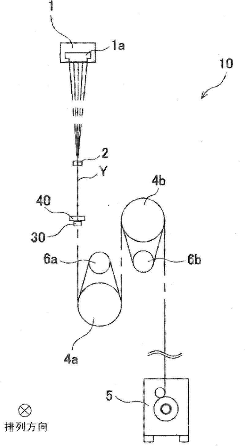
[0027] Next, embodiments of the present invention will be described. figure 1 It is a side view showing the general structure of the spinning coiler. Such as figure 1 As shown, the spinning coiler 10 attaches the oil agent through the oil supply nozzle 2 to the yarn Y having a plurality of filaments discharged from the spinning nozzle 1a of the spinning machine 1 above, and then uses two godet rollers to 4a and 4b stretch the yarn Y, and then transport it to the yarn winding device 5 located below and wind it up.

[0028] A plurality of filaments Y provided with a plurality of filaments are discharged from the spinneret 1a of the spinning machine 1, and these plurality of filaments Y are figure 1 A plurality of them are arranged in a direction (hereinafter referred to as an arrangement direction) perpendicular to the paper surface and run. The oil supply nozzle 2 sprays and deposits oil on the yarn Y having a plurality of filaments fed from the spinning machine 1 .

[0...


PUM


Abstract

All yarns are surely cut and sucked irrespective of the number of the yarns. A yarn cutting-sucking device 40 includes a cutter 43 arranged to be movable in the alignment directions of yarns Y, a sucking unit 41 which is provided in proximity to the cutter 43 and includes a sucking pipe 45 which is movable in the alignment directions in the same manner as the cutter 43, and a cylinder 46 which is arranged to move the sucking pipe 45 along the alignment directions. As the cylinder 46 is driven, the cutter 43 and the sucking pipe 45 move in an alignment direction in a synchronous manner.

Description

technical field [0001] The invention relates to a yarn cutting suction device and a spinning coiler. Background technique [0002] For example, in a machine that processes a plurality of yarns that are arranged in one direction and continuously supplied continuously, such as a spinning winder that winds a plurality of yarns after spinning, even if the treatment is interrupted, the spinning The plurality of yarns that have been spun out are also continuously fed out, so a yarn cutting and suction device is provided to cut and suck the plurality of yarns that are continuously fed out, and to hold them while the downstream processing is interrupted. As a device for cutting and aspirating a plurality of filaments in this way, in the filament cutting and suction device of Patent Document 1, a plurality of filaments are approached to the central side through the wire guide plate from both sides in the arrangement direction, and are locked together to the filament storage guide. o...

Claims


Application Information

Patent Timeline
Patent Type & Authority Applications(China)
IPC IPC(8): B65H54/71B65H54/88
CPCB65H54/71B65H54/88B65H57/16B65H2701/3132B65H2701/38
Inventor 桥本欣三岸根章典
Owner TMT MACHINERY INC
Why Eureka
Try Eureka