Web cutting device

A technology of cutting device and web, which is applied in the direction of winding strips, transportation and packaging, printing, etc., can solve the problems of reduced reliability of the device, large number of parts, increased cost, etc., to ensure stability, simplify the structure, The effect of improving reliability

Inactive Publication Date: 2012-07-11
KOMORI CORP
View PDF6 Cites 7 Cited by
  • Summary
  • Abstract
  • Description
  • Claims
  • Application Information

AI Technical Summary

Problems solved by technology

[0008] However, in the roll paper cutting device of Patent Document 1, since the approaching mechanism 104 is composed of two link assemblies 105a, 105b, the link assemblies 105a, 105b have the first link 107, the second link 110, the second One to the third support shaft 106, 109, 113 and support shaft 114, and the long hole 112, so the structure is complex and the number of parts is large, resulting in an increase in cost
[0009] In addition, the connecting portion of the first and second links 107, 110 connected with the second support shaft 109, the connecting portion of the second link 110 and the pressing member 111 connected with the support shaft 114, and the connection portion of the second link 110 connected with the support shaft 114, and The connecting part of the second connecting rod 110 and the blade 102 connected by 113 will be scratched, which will reduce the reliability of the device

Method used


Image

  • Web cutting device
  • Web cutting device
  • Web cutting device

Examples


Embodiment 1

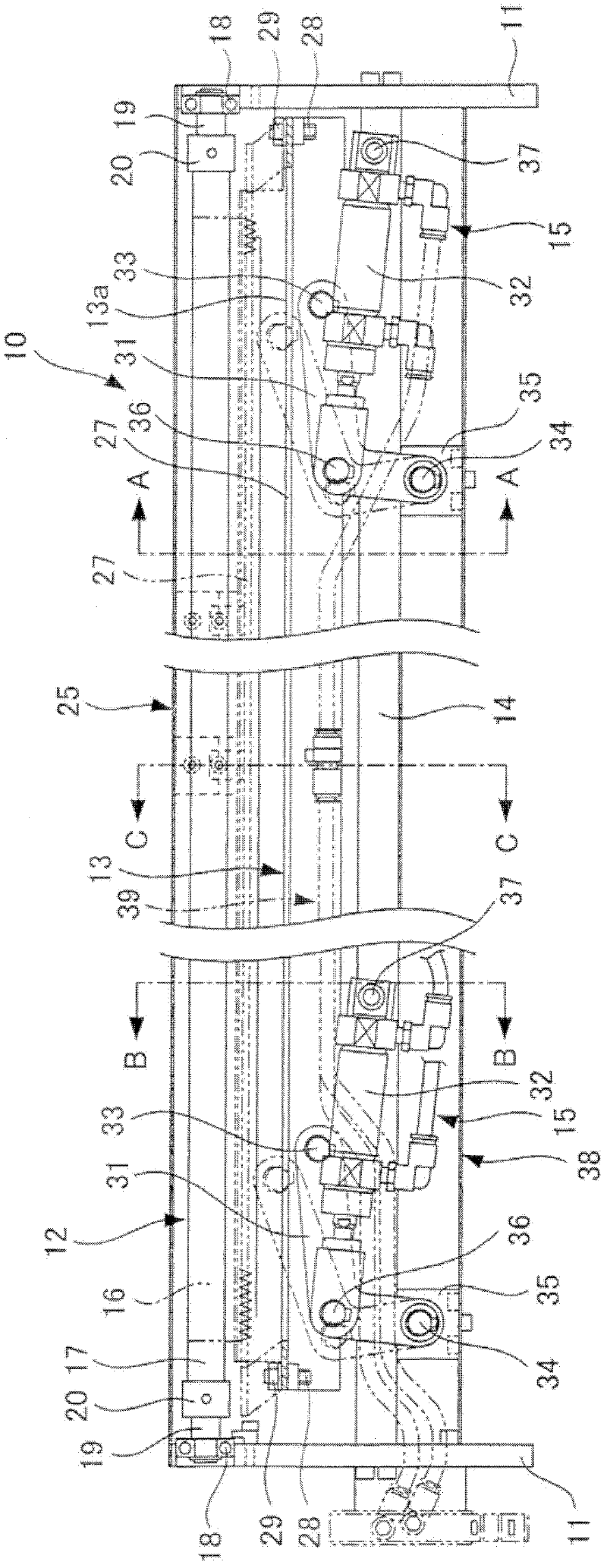
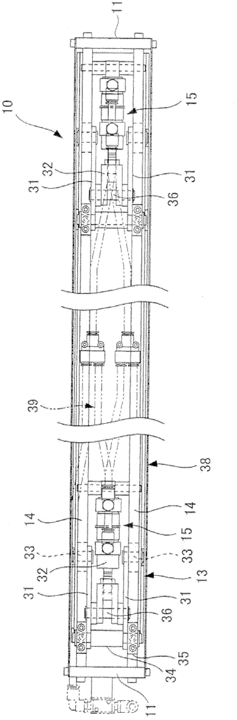
[0070] figure 1 is a front sectional view showing a roll paper cutting device according to Embodiment 1 of the present invention, figure 2 is a bottom sectional view of the web cutting device, image 3 is a top sectional view of the web cutting device, Figure 4A yes figure 1 A-A line sectional view of Figure 4B yes figure 1 B-B line sectional view, Figure 4C yes figure 1 The C-C line section diagram, Figure 5 It is the action state diagram of the web cutting device, Figure 5 (a) is the position of the knife when the positioning bolt touches the initial stage, Figure 5 (b) is the position of the knife when the positioning bolt abuts halfway, Figure 5 (c) is the position of the knife when the positioning bolt is pressed and cut.

[0071] As shown in the figure, the cutter support member 12 of the web cutting device 10 of the offset rotary printing machine is rotatably erected between the left and right side frames 11, and the cutter receiving member 13 is l...

Embodiment 2

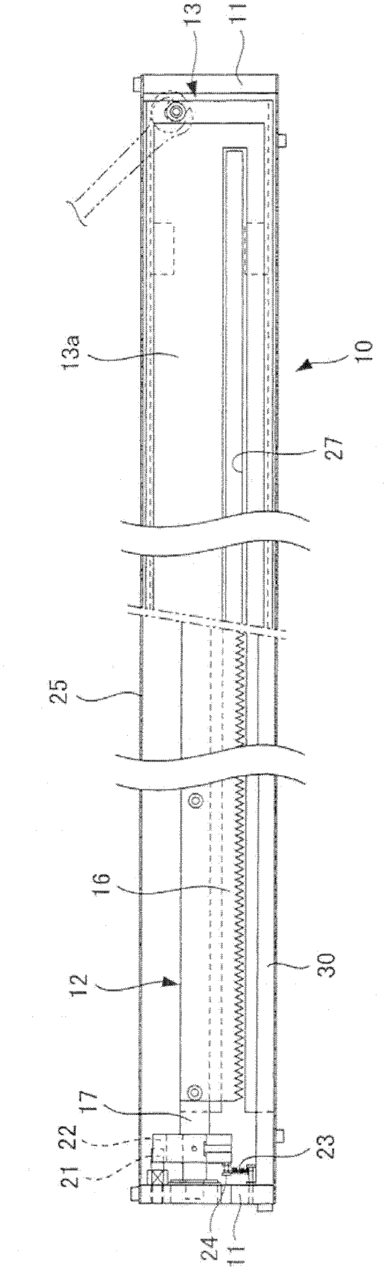
[0089] Image 6 It is a top sectional view showing a roll paper cutting device according to Embodiment 2 of the present invention.

[0090] In this example, instead of the slit (blade receiving portion) 27 provided on the top surface portion 13a of the cutter receiving member 13 in Embodiment 1, a plurality of engaging knives are arranged in a row corresponding to each serration 16a of the serrated knife 16. Hole (blade receiving part) 40. Other structures are identical with embodiment 1, and image 3 The same components are given the same reference numerals, and repeated explanations are omitted.

[0091] According to this embodiment, in addition to having the same action and effect as Embodiment 1, it also has the following advantages: when cutting, the web W is pressed against the portion (top portion 13a) between the engaging knife holes 40, The roll paper W can be accurately scored without slack downward, and since the roll paper W is stretched by the front portion, cu...


PUM


Abstract

A web cutting device, which achieves cost reduction by a simplified structure, ensures operational stability, and enhances the reliability of the device, is provided. The web cutting device (10), is equipped with a cutting blade (16) for cutting a web (W), and comprises: a cutting blade support member (12) supporting the cutting blade and supported to be pivotable between a standby position and a cutting position; a return spring (23) for urging the cutting blade support member toward the standby position; a stopper pin (21) and an engaging groove (22) for stopping the cutting blade support member at least at the standby position; a cutting blade bearing member (13) provided with a slit (27) for receiving the cutting blade, and a knock bolt (28) for pivoting the cutting blade support member to the cutting position; and drive means (15), composed of an L-shaped lever (31) and an air cylinder (32), for moving the cutting blade bearing member toward and away from the cutting blade support member.

Description

technical field [0001] The invention relates to a roll paper cutting device of an offset rotary printing machine for printing on roll paper. Background technique [0002] In the past, when the web was broken (broken) in the offset rotary printing machine that printed on the web, the web was wrapped around the circumferential surface of the rubber cylinder due to the adhesive force of the ink, and the rubber was damaged. Accidents such as roller bearings or roller shafts. [0003] Therefore, as disclosed in Patent Document 1 (European Patent No. 0686505 specification) and the like, a web is provided on the traveling path of the web (for example, between each printing unit and between the final printing unit and the dryer). Paper cutting device, which cuts the roll paper at the same time when the roll paper is detected, so that the length of the roll paper wound on the blanket cylinder is minimized, so that the blanket cylinder will not be damaged Accidents such as bearings ...

Claims


Application Information

Patent Timeline
Patent Type & Authority Applications(China)
IPC IPC(8): B41F13/60
CPCB65H35/04B41F33/0018B41F13/60B65H35/10B26D1/065B65H2601/26B65H26/025B26D5/12B41P2233/21B26F3/02B26D5/18B41F33/18Y10T83/8749
Inventor 田村直文铃木元辉
Owner KOMORI CORP
Why Eureka
Try Eureka