Transmitter

a transmitter and transmitter technology, applied in the field of wireless transmitters, can solve the problems of power consumption, problem in practical use, and the inability of conventional class-a or class-ab high-frequency power amplifiers to achieve high efficiency, and achieve the effect of high efficiency operation

Inactive Publication Date: 2006-10-03
PANASONIC CORP
View PDF14 Cites 42 Cited by
  • Summary
  • Abstract
  • Description
  • Claims
  • Application Information

AI Technical Summary

Benefits of technology

[0018]With this configuration, the invention adopts a configuration wherein the plurality of switching regulators for converting the power supply voltage into the plurality of voltages having different values stepwise are provided, one of the switching regulators is selected depending on the level of the amplitude component, and the linear voltage converting means voltage-converts the amplitude component by using the output voltage of the selected switching regulator as the power supply voltage. Hence, the voltage drop due to the linear voltage converting means can be lowered, whereby the loss due to the switching regulators can be decreased, and the power loss due to the linear voltage converting means can also be decreased. Furthermore, since the linear voltage converting means is used for the voltage conversion, it is not necessary to use a low-pass filter at its output section, whereby broadband can be attained. Therefore, it is possible to attain the EER method in a wide frequency band without lowering efficiency.
[0051]In accordance with the present invention as described above in detail, in the EER method capable of operating the high-frequency power amplifier as a switch type, highly efficient operation is made possible in a wide frequency band.

Problems solved by technology

However, as broadband communication is promoted, a communication system that uses subcarriers, such as OFDM (Orthogonal Frequency Division Multiplex), has begun to be used; hence the conventional class-A or class-AB high-frequency power amplifier cannot be expected to attain high efficiency.
For this reason, in the case of a portable wireless transmitter wherein batteries are used as a power supply, its operable time is short, thereby causing a problem in practical use.
The conventional class-A amplifier has a period in which the drain voltage and the drain current are generated simultaneously, thereby consuming power.
However, since the switch-type amplifier is a nonlinear amplifier, the switch-type amplifier cannot be used because a modulated signal, such as the QAM signal, in which the amplitude level of the modulated wave changes, is required to be amplified linearly.
However, since the frequency band of the voltage converter 42 (for example, a switching regulator) for modulating the amplitude component is 5 MHz at most, the conventional EER method cannot be used in the modulated wave frequency band width of 20 MHz stipulated in the IEEE802.11a Standard, a wireless LAN standard.
However, since the Q value of the inductance is lowered, the amount of heat consumed by the inductance becomes unignorable, and the efficiency of the voltage converter 42 lowers.
In addition, noise increases.
Furthermore, in the case when a series regulator is used as the voltage converter 42, the product of the amount of voltage conversion (the difference between the power supply voltage and the voltage of the amplitude component) of the series regulator and the drain current of the high-frequency power amplifier is power consumption.

Method used


Image

  • Transmitter
  • Transmitter
  • Transmitter

Examples


embodiment 1

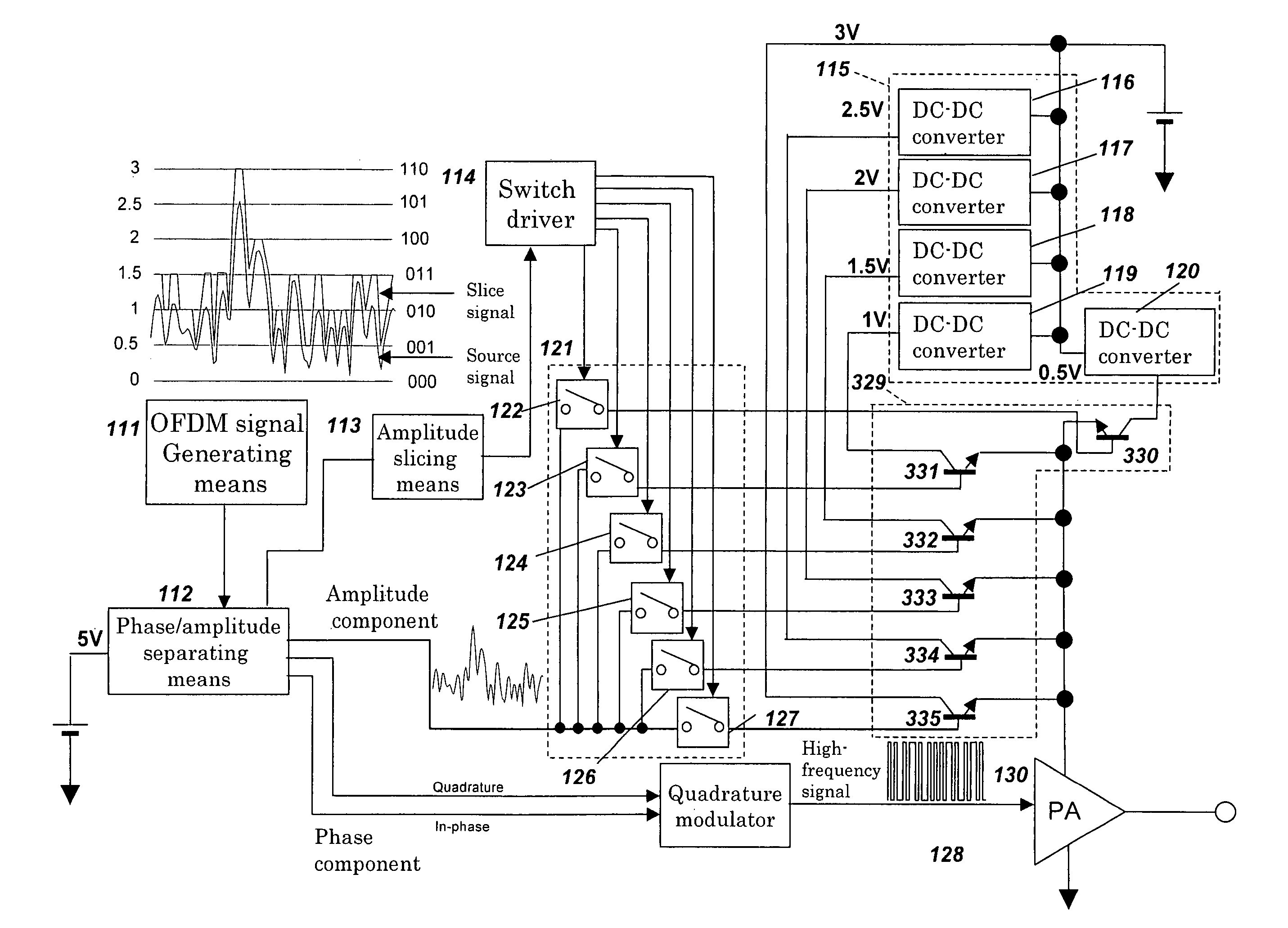
[0065]Embodiment 1 in accordance with the present invention will be described below referring to the drawing. In this embodiment, the wireless LAN system according to the IEEE802.11a Standard, wherein a wideband modulated signal is used, is taken as an example and explained. In the wireless LAN system, each of 52 quadrature subcarriers is subjected to 64-QAM modulation, and these are added to obtain a modulated signal. The 52 subcarriers are respectively spaced 312.5 kHz apart, thereby occupying 52×312.5=16.25 MHz.

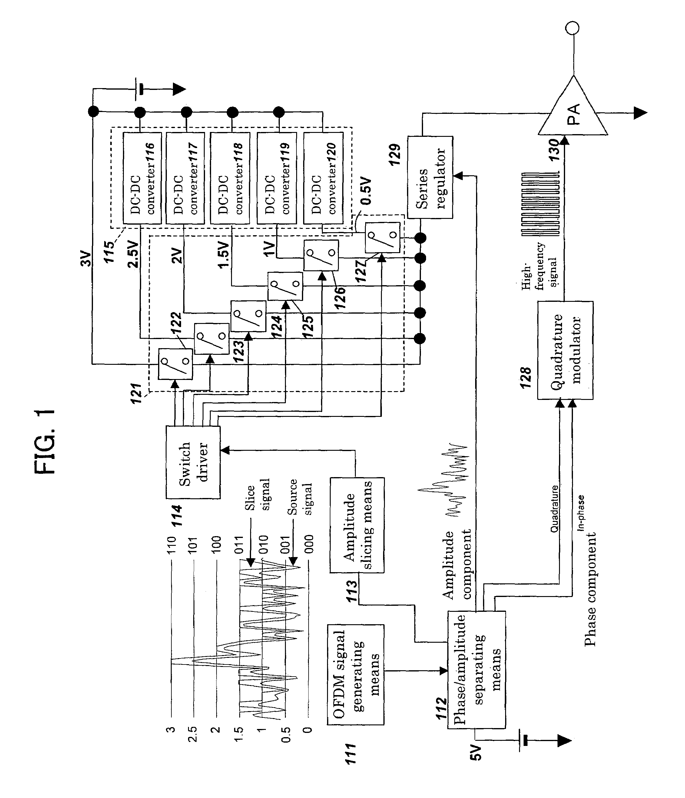
[0066]FIG. 1 is a circuit diagram of a transmitter in accordance with Embodiment 1 of the present invention for attaining the EER method. As shown in FIG. 1, this transmitter comprises OFDM signal generating means 111, phase / amplitude separating means 112, amplitude slicing means 113, a switching regulator group 115, a switch group 121, a switch driver 114, a quadrature modulator 128, a series regulator 129, and a switch-type high-frequency power amplifier 130.

[0067]The ab...

embodiment 2

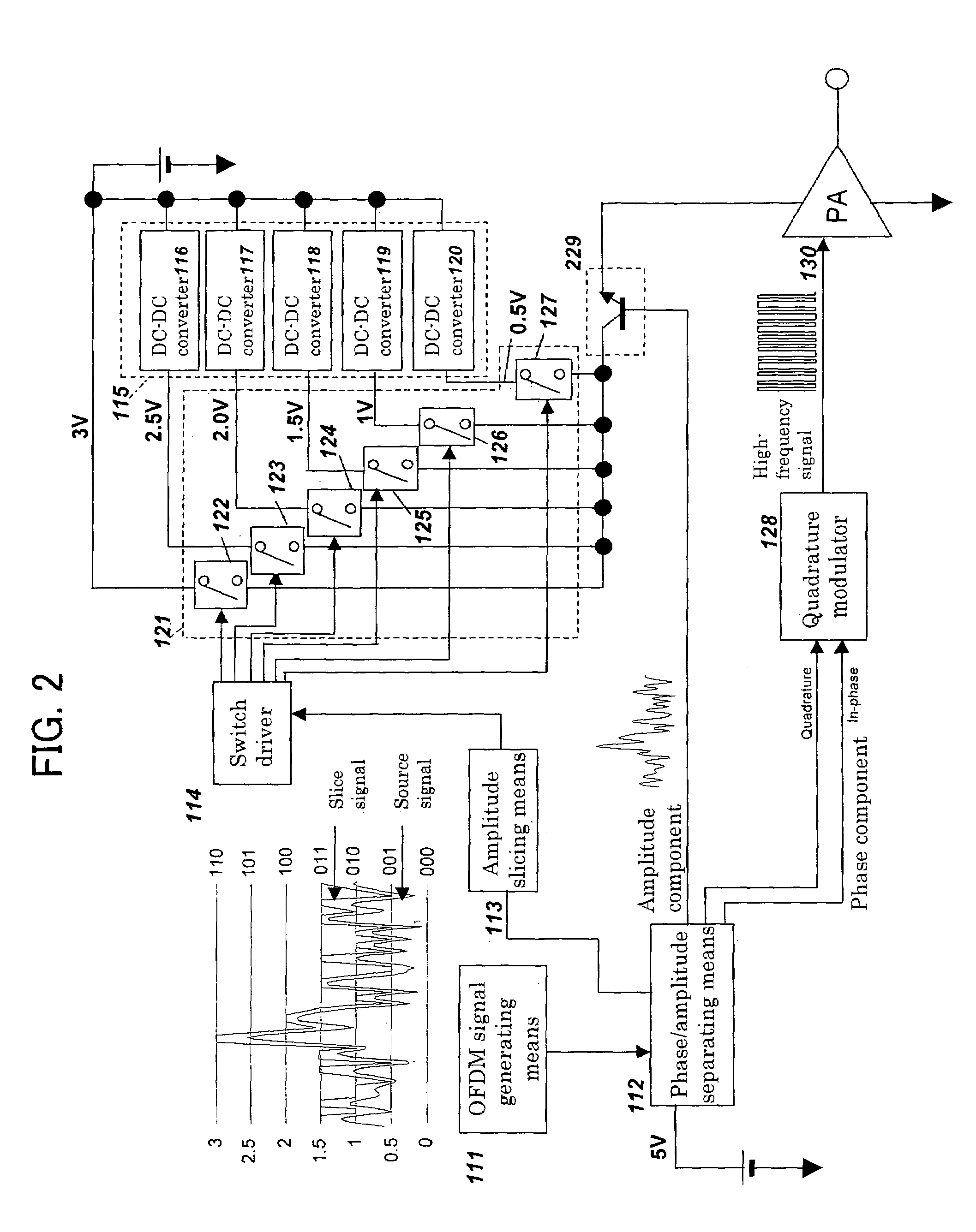
[0121]FIG. 2 is a block diagram of a transmitter in accordance with Embodiment 2 of the present invention. This embodiment differs from Embodiment 1 in that an emitter follower 229 is used instead of the series regulator 129. Except for this, this embodiment is the same as Embodiment 6 in configuration and operation; hence, the components are designated by the same numerals and their explanations are omitted. The emitter follower 229 receives the outputs of the switch group 121 at the collector and applies the power supply voltage to the high-frequency power amplifier 130 on the basis of the voltage of the phase / amplitude separating means 112 having been input to the base.

[0122]An effect additionally obtained by using the emitter follower 229 is described below. In the case of the series regulator, a sufficient frequency band is not obtained in some cases owing to a phase delay due to the feedback loop or the like. On the other hand, in the case of using the emitter follower 229, th...

embodiment 3

[0123]FIG. 3 is a block diagram of a transmitter in accordance with Embodiment 8 of the present invention. This embodiment differs from Embodiments 1 and 2 in that the outputs from the power supply and the DC—DC converter group 115 are directly connected to the collectors of an emitter follower group 329 as many as the outputs, and that the bus connected to the base terminals of this emitter follower group 329 is switched by the switch group 121 comprising switches as many as the emitter followers of the emitter follower group 329. The same components as those of Embodiments 1 and 2 are designated by the same numerals and their explanations are omitted. The emitter follower group 329 corresponds to linear voltage converting means. It is preferable that the switch group 121 is formed of NMOS transistors. In addition, although this embodiment uses the plurality of emitter followers, an embodiment using series regulators instead of the emitter followers can also be devised in a way sim...


PUM


Abstract

The present invention provides a transmitter conforming to the EER method in a wide frequency band at high efficiency. For this purpose, the amplitude component of a modulated signal is input to the power supply terminal of a high-frequency power amplifier 130, the I and Q quadrature signals thereof are input to the high-frequency input terminal of the high-frequency power amplifier 130, and the original modulated signal is obtained from the output of the high-frequency power amplifier 130. A collector voltage is supplied from DC—DC converter group 615 having output voltages being different sequentially to an emitter follower 729 via a switch group 621. One of the outputs of the DC—DC converters 616 to 620 is selected depending on the level of the amplitude component as the collector voltage and supplied to the emitter follower, whereby the difference between the emitter voltage of he emitter follower 729 and the collector voltage of the emitter follower 729 is made smaller and the efficiency of the emitter follower 729 is raised; furthermore, the power supply voltage of the high-frequency power amplifier 130 is voltage-converted by the emitter follower 729, whereby operation in a wide frequency band is made possible.

Description

TECHNICAL FIELD[0001]The present invention relates to a wireless transmitter for use in a communication system that uses subcarriers, such as OFDM (Orthogonal Frequency Division Multiplex).BACKGROUND TECHNOLOGY[0002]In a modulated signal subjected to voltage conversion, in particular, a modulated signal subjected to multi-level modulation, such as QAM (Quadrature Amplitude Modulation), linear operation is required in a high-frequency power amplifier for transmitting power to an antenna. Hence, class A or class AB has been used as the operation class of the high-frequency power amplifier.[0003]However, as broadband communication is promoted, a communication system that uses subcarriers, such as OFDM (Orthogonal Frequency Division Multiplex), has begun to be used; hence the conventional class-A or class-AB high-frequency power amplifier cannot be expected to attain high efficiency. In other words, in OFDM, subcarriers are overlapping, whereby high power is generated instantaneously at...

Claims


Application Information

Patent Timeline
Patent Type & Authority Patents(United States)
IPC IPC(8): H04B1/02H01Q11/12H04B1/04H03F1/02
CPCH03F1/0244H03F1/025H04B2001/045H03F1/02H03F3/24H03F2200/511H03F2200/507
Inventor TANABE, MITSURUSAEKI, TAKAHARUMINAMI, YOSHIHISATANAKA, KOICHIROSAITO, NORIAKI
Owner PANASONIC CORP
Why Eureka
Try Eureka