
Road shoulder maintenance machine

A technology for maintaining machines and road shoulders, which is applied in the directions of roads, roads, road repair, etc., can solve the problems of inconvenient lifting mechanism, clumsy work, high labor intensity, etc., and achieve the effect of remarkable work effect, simple overall structure and flexible lifting mechanism.

Active Publication Date: 2013-08-07
薛纯
View PDF10 Cites 0 Cited by
  • Summary
  • Abstract
  • Description
  • Claims
  • Application Information

AI Technical Summary

Problems solved by technology

[0002] The shoulders of the road will be uneven after being washed by rainwater and rolled by vehicles. In addition, wild weeds on the side slopes of the road shoulders will seriously affect the drainage of the road surface, accelerate the damage of the road surface, and shorten the service life of the road surface.
In the past, the maintenance of road shoulders was done manually with shovel tools to complete various tasks such as clearing the slope, weeding and repairing, and then rolling and leveling. This operation is labor-intensive and low-efficiency
At present, professional machinery in this area is very scarce in the market. The patent number is: 201220395217.3 "Road Shoulder Maintenance Machine", which solves the above problems, but because its overall design is not very reasonable, it is clumsy to work, especially on the shoulder of the road. The efficiency of the compaction link is not high, it is only compacted by the weight of the compaction roller itself, and the desired effect cannot be achieved
In addition, the roadside slope lifting mechanism is inconvenient and inflexible, with poor working quality and low efficiency

Method used


Image

  • Road shoulder maintenance machine

Examples


Embodiment Construction

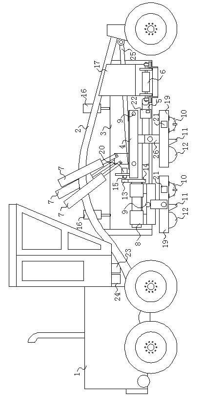
[0012] Attached below figure 1 A kind of road shoulder maintenance machine of invention, make further explanation:

[0013] The road shoulder maintenance machine of the present invention is composed of a locomotive, a vehicle frame, a hopper and a repair mechanism. The rear end of the vehicle frame 2 is fixedly connected to the front end of the locomotive 1, and a hopper 3 and a front part of the hopper 3 are installed on one side of the vehicle frame 2. A discharge port 17 is provided, a longitudinal conveyer belt 5 is arranged at the bottom of the hopper 3, a transverse conveyer belt 6 is arranged at the discharge port 17 at the front end of the longitudinal conveyer belt 5, the road shoulder repair mechanism frame 4 is connected with the vehicle frame 2 through a connecting rod 25, and The road shoulder repair mechanism frame 4 rear side is connected with the roadside slope repair mechanism frame 8. The road shoulder repair mechanism frame 4 and the roadside slope repair m...


PUM


Abstract

The invention discloses a road shoulder maintenance machine which belongs to auxiliary equipment for road repairing. The road shoulder maintenance machine comprises a locomotive, a frame, a hopper and a repairing mechanism, wherein the tail end of the frame is fixedly connected with the front end of the locomotive; the hopper is mounted on one side of the frame; a discharging hole is formed in the front part of the hopper; a longitudinal conveying belt is arranged at the lower part of the hopper; a transverse conveying belt is arranged at the front end of the longitudinal conveying belt; a road shoulder repairing mechanism frame is connected with the frame; the rear side of the road shoulder repairing mechanism frame is connected with a roadside slope repairing mechanism frame; road shoulder levelers are arranged on both the road shoulder repairing mechanism frame and the roadside slope repairing mechanism frame; a frame tilt adjustment oil cylinder is fixed to the frame and hinged with the top of the road shoulder repairing mechanism frame; a rear tilt mechanism motor is arranged on the road shoulder repairing mechanism frame; and an output shaft of the rear tilt mechanism motor is connected with a transmission wheel on the roadside slope repairing mechanism frame in a transmission way. The road shoulder maintenance machine is reasonable in structure design, remarkable in working effect and flexible for a roadside slope lifting mechanism, can effectively supplement and firmly compact soil for road shoulders, is high in working efficiency, replaces manual operation, and is time-saving and labor-saving.

Description

technical field [0001] The invention belongs to auxiliary equipment for repairing roads, in particular to a road shoulder maintenance machine. Background technique [0002] The shoulder of the road will be uneven after being washed by rainwater and rolled by vehicles. In addition, wild weeds on the side slope of the road shoulder will seriously affect the drainage of the road surface, accelerate the damage of the road surface, and shorten the service life of the road surface. In the past, the maintenance of road shoulders was done manually with shovel tools to complete various tasks such as slope removal, weeding, and renovation, and then rolled and leveled. This operation is labor-intensive and low-efficiency. At present, professional machinery in this area is very scarce in the market. The patent number is: 201220395217.3 "Road Shoulder Maintenance Machine", which solves the above problems, but because its overall design is not very reasonable, it is clumsy to work, especi...

Claims


Application Information

Patent Timeline
IPC IPC(8): E01C23/00
Inventor 高小林
Owner 薛纯
Learn More