
Suspension structure, bush structure and suspension characteristic adjusting method
a suspension structure and bush structure technology, applied in the direction of shock absorbers, manufacturing tools, transportation and packaging, etc., can solve the problems of difficult to shift the resonance point to the higher frequency side, difficult to increase the stiffness of the bush in the axial direction, etc., to improve the sound and vibration performance, increase the stiffness of the bush, and reduce the stiffness
- Summary
- Abstract
- Description
- Claims
- Application Information
AI Technical Summary
Benefits of technology
Problems solved by technology
Method used
Image

Examples
Embodiment Construction
[0035]The following is explanation on vehicles such as motor vehicles according to embodiments of the present invention, with reference to drawings.
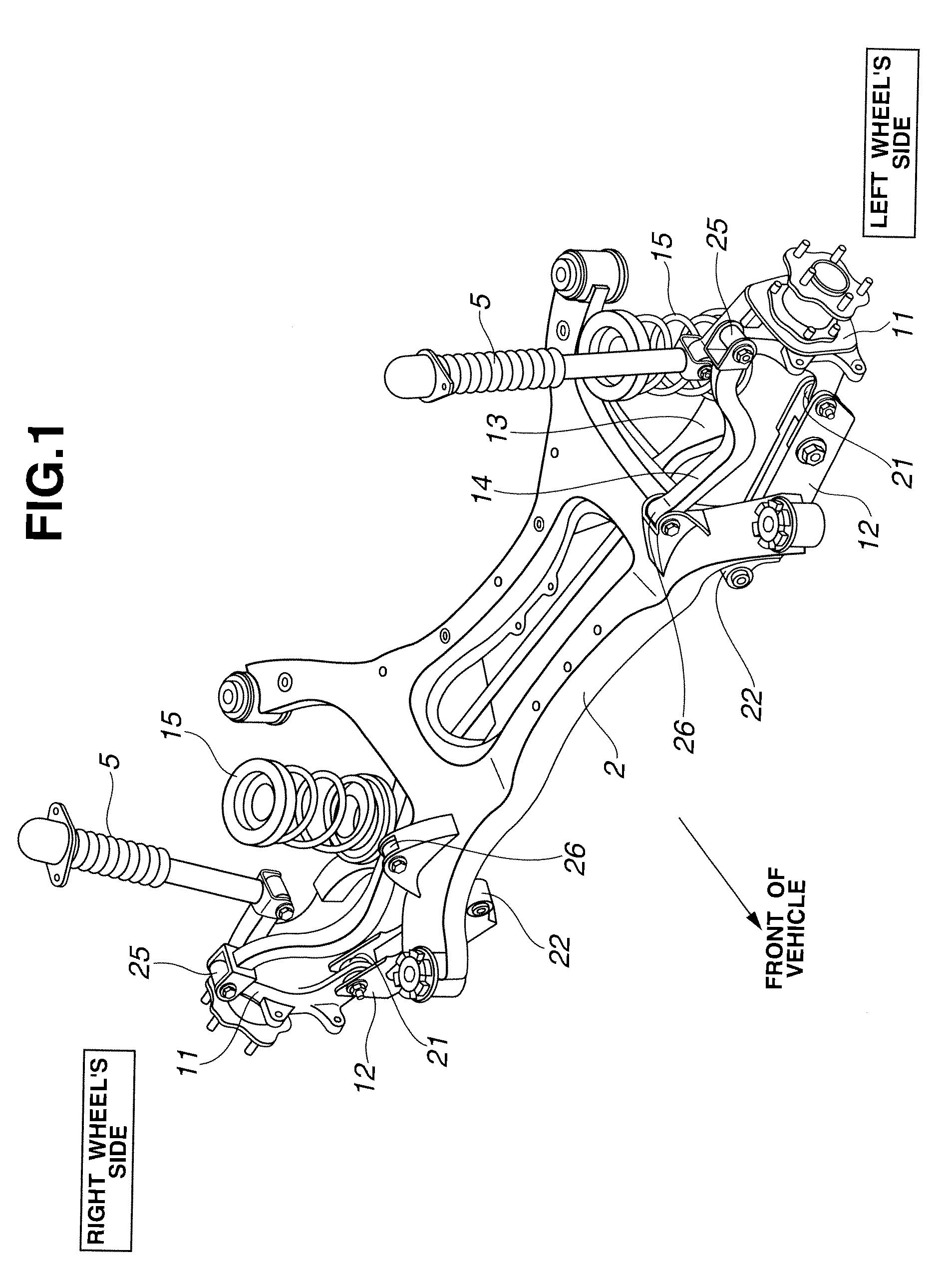
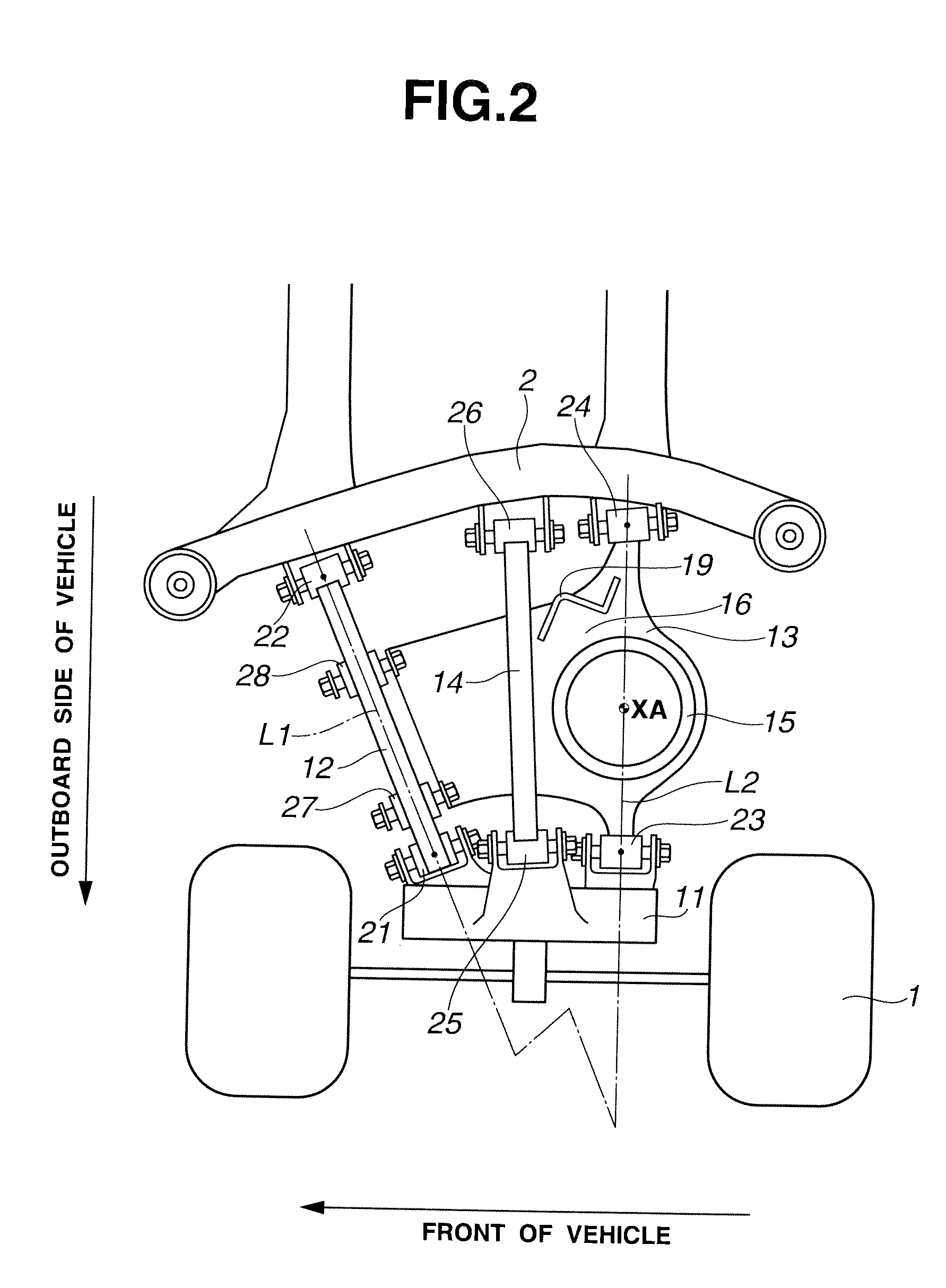
[0036]FIG. 1 is a perspective view schematically showing a rear wheel suspension system in perspective. FIG. 2 is schematic top view schematically showing a rear left wheel suspension system. FIG. 3 is a schematic front view schematically showing the rear left wheel suspension system.
[0037]In the illustrated example of this embodiment, a rear left wheel independent suspension system or structure is taken as an example. The suspension system shown in FIGS. 2 and 3 connects a wheel 1 to a suspension member 2 (vehicle body member) of a vehicle body, and includes an axle housing 11 (hub carrier), a lower front link 12 (front suspension link), a lower rear link 13 (rear suspension link), an upper link 14, a coil spring 15 and a strut 5 (shown in FIG. 1). Axle housing 11 is a wheel support member supporting the wheel 1 rotatably.
[0038]The lowe...
PUM
| Property | Measurement | Unit |
|---|---|---|
| Thickness | aaaaa | aaaaa |
Abstract
Description
Claims
Application Information