
Methods and apparatus for improving sound within an acoustical boundary layer

a technology of acoustic boundary layer and fluid dynamics, applied in the field of fluid dynamics, can solve problems such as acoustic noise, unwanted distortion, and acoustic noise within the boundary layer between the mean flow and the surface, and achieve the effect of improving the fluid dynamics of the acoustic boundary layer and improving performan

Active Publication Date: 2019-02-21
OUT OF THE BOX AUDIO LLC
View PDF9 Cites 2 Cited by
  • Summary
  • Abstract
  • Description
  • Claims
  • Application Information

AI Technical Summary

Benefits of technology

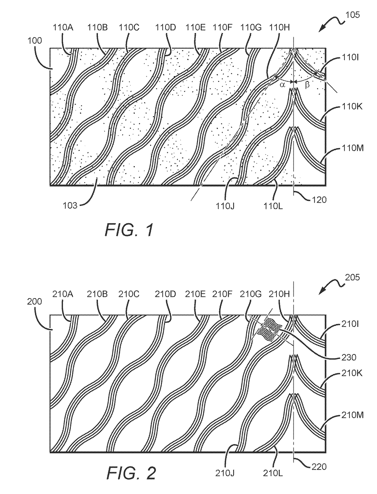
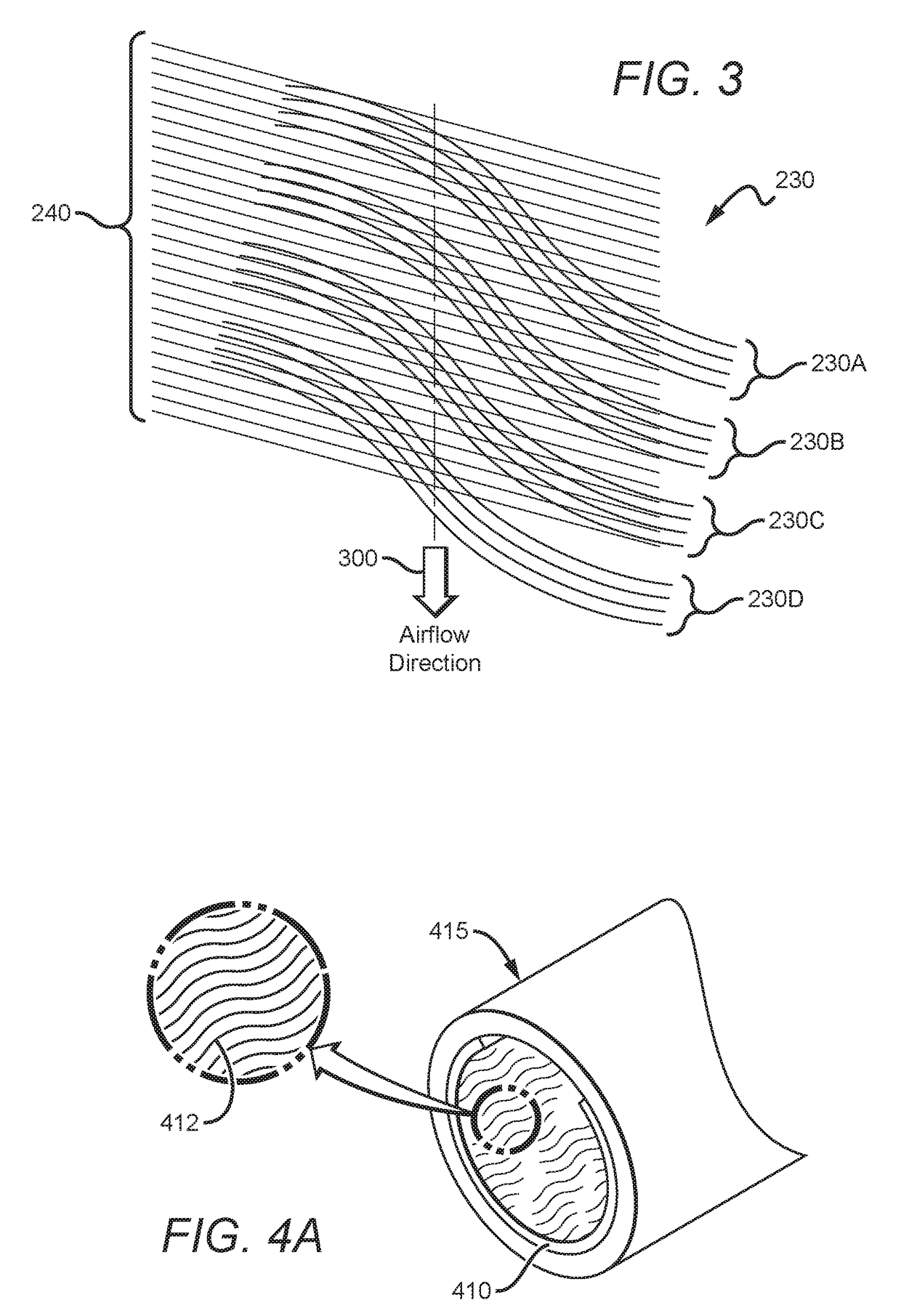
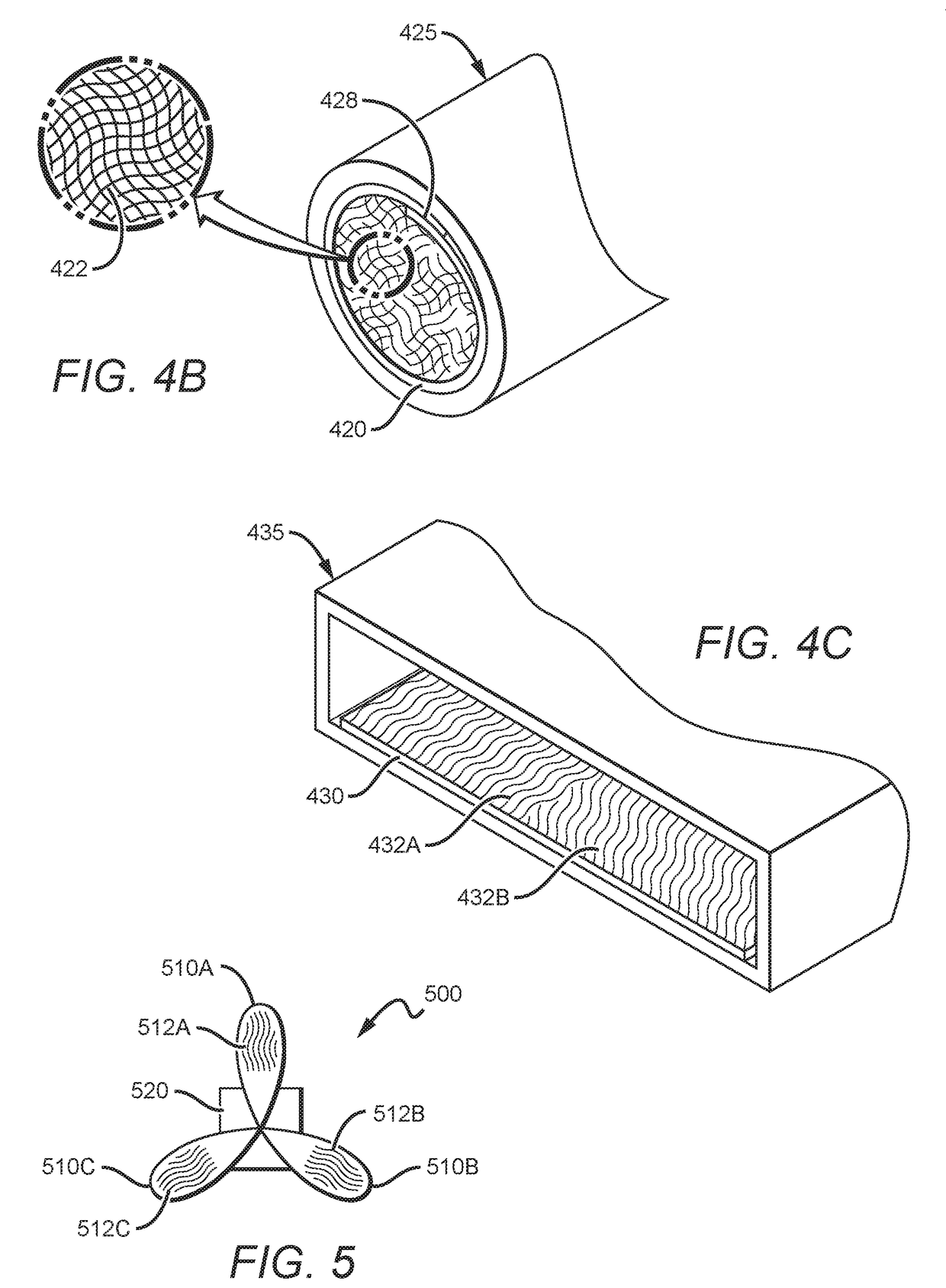
This patent discusses the use of wavy riblets on the surface of sound producing devices to improve their sound performance. Riblets are small grooves or protrusions that are intentionally deployed on a surface and can reduce distortion, improve transmission of desired frequencies, and reduce the sound of air flow. They can be optimized for different purposes by varying their orientation, size, and proximity to other riblets. The patent also mentions the benefits of arranging riblets in herringbone patterns, which can improve the fluid dynamics of the acoustic boundary layer on the surface. Overall, the patent provides a technical solution for enhancing the sound quality of sound producing devices through the use of wavy riblets.

Problems solved by technology

In any device in which air or other fluid moves across a surface, there is turbulence within the boundary layer between the mean flow and the surface, especially when the airflow in a passageway becomes faster in speed.
In some instances that turbulence is desirable, and in other instances that turbulence can be problematic.
In speaker port ducts, microphones, and musical instruments passageways, turbulence and associated vortex shedding is a cause of acoustical noise and unwanted distortions.
But larger port bores do not eliminate turbulence within the boundary layer.
But none of those technologies adequately addresses the root problem of distortions that a port duct has on a complex sound wave moving through or over a turbulent boundary layer.

Method used


Image

  • Methods and apparatus for improving sound within an acoustical boundary layer
  • Methods and apparatus for improving sound within an acoustical boundary layer
  • Methods and apparatus for improving sound within an acoustical boundary layer

Examples


Embodiment Construction

[0042]The following description includes information that may be useful in understanding the present invention. It is not an admission that any of the information provided herein is prior art or relevant to the presently claimed invention, or that any publication specifically or implicitly referenced is prior art.

[0043]Although each described embodiment represents a single combination of inventive elements, the inventive subject matter is considered to include all possible combinations of the disclosed elements. Thus if one embodiment comprises elements A, B, and C, and a second embodiment comprises elements B and D, then the inventive subject matter is also considered to include other remaining combinations of A, B, C, or D, even if not explicitly disclosed.

[0044]As used herein, and unless the context dictates otherwise, the term “coupled to” is intended to include both direct coupling (in which two elements that are coupled to each other contact each other) and indirect coupling (...


PUM


Abstract

Wavy riblets are disposed at one or more auditorily important acoustical boundary layers of a sound producing device. Wavy riblets can be deployed directly onto the surface of the device, and / or onto a film or other carrier that is then positioned in or on the device. Wavy riblets can be advantageously deployed in sets, in a herringbone pattern, and sets of smaller riblets can be disposed between sets of larger riblets. Wavy riblets can also be superimposed onto other wavy or non-wavy riblets. Contemplated sound producing devices include speakers, musical instruments, fan blades and ducts.

Description

[0001]This application claims priority to U.S. provisional application Ser. No. 62 / 548,343 filed Aug. 21, 2017, which is incorporated herein in its entirety.FIELD OF THE INVENTION[0002]The field of the invention is fluid dynamics, and especially acoustic fluid dynamics.BACKGROUND[0003]The background description includes information that may be useful in understanding the present invention. It is not an admission that any of the information provided herein is prior art or relevant to the presently claimed invention, or that any publication specifically or implicitly referenced is prior art.[0004]In any device in which air or other fluid moves across a surface, there is turbulence within the boundary layer between the mean flow and the surface, especially when the airflow in a passageway becomes faster in speed. In some instances that turbulence is desirable, and in other instances that turbulence can be problematic.[0005]In speaker port ducts, microphones, and musical instruments pas...

Claims


Application Information

Patent Timeline
Patent Type & Authority Applications(United States)
IPC IPC(8): F15D1/00H04R1/28
CPCF15D1/0035H04R1/2811H04R1/288H04R1/2803H04R1/30
Inventor PAULEY, DOUGLAS K.
Owner OUT OF THE BOX AUDIO LLC
Learn More