Suspension structure and method of making suspension link
Active Publication Date: 2012-11-22
NISSAN MOTOR CO LTD
View PDF12 Cites 3 Cited by
Summary
Abstract
Description
Claims
Application Information
AI Technical Summary
This helps you quickly interpret patents by identifying the three key elements:
Problems solved by technology
Method used
Benefits of technology
Benefits of technology
[0003]It is, therefore, in view of the previously-described disadvantages of the prior art, an object of the invention to provide a suspension structure and a method of making a suspension link, by which the durability of the suspension link can be certainly enhanced, thereby ensuring the increased life of the suspension system.
Problems solved by technology
In such a hollow-structure suspension link as disclosed in WO2005 / 002890, there is a possibility of reduced durability of the suspension link owing to the occurrence of a stress concentration (high localized stresses) in the suspension link, induced by a load input from a coil spring, a shock absorber, a stabilizer, and so forth.
Method used
Image
Click on the blue label to locate the original text in one second.
Reading with bidirectional positioning of images and text.
Examples
first embodiment
[Construction]
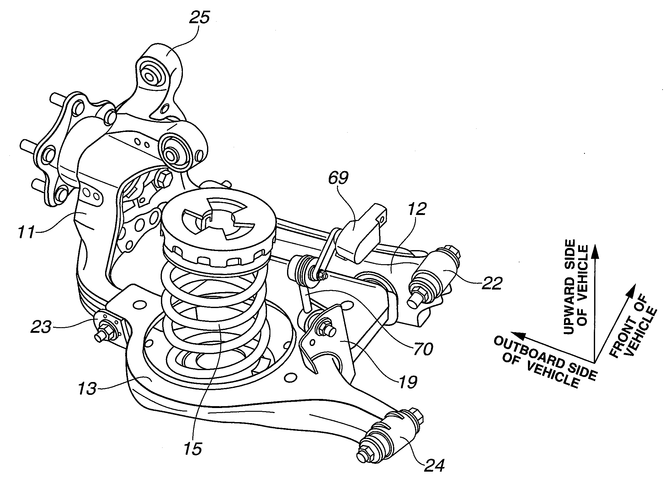
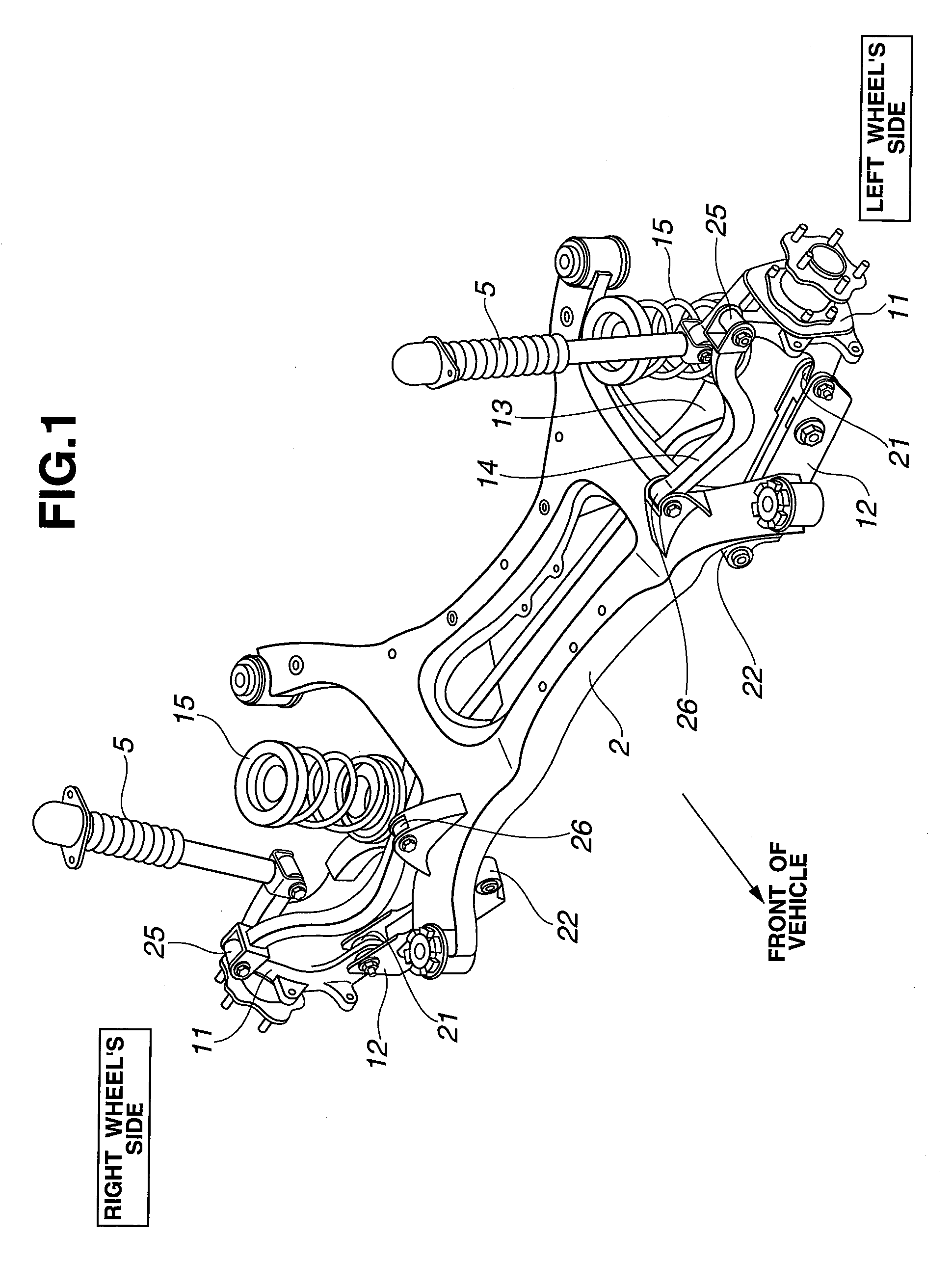
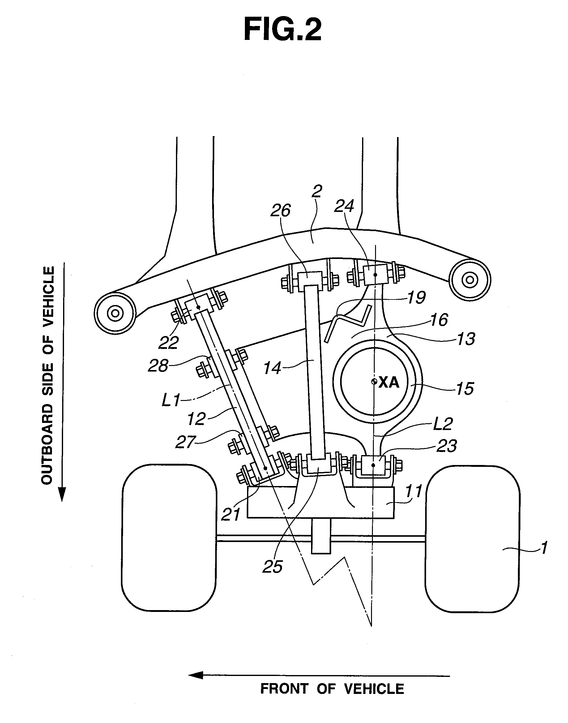
[0021]FIG. 1 is the perspective view illustrating the construction of the multi-link rear suspension of the embodiment under an assembled state. FIG. 2 is the top view illustrating the construction of the rear-left suspension of the embodiment under the assembled state. FIG. 3 is the front elevation view illustrating the construction of the rear-left suspension of the embodiment under the assembled state.
[0022]The suspension structure of the embodiment is exemplified in an independently-suspended rear-left road-wheel suspension, simply, an independent rear-left suspension.
[0023]As shown in FIG. 1, the suspension structure is provided for suspending a road wheel 1 from a suspension member 2 of the vehicle-body side, and comprised of an axle housing 11 (a hub carrier), a lower front link 12, a lower rear link 13, an upper link 14, a coil spring 15, and a strut 5.
[0024]Axle housing 11 is configured to rotatably support the road wheel 1.
[0025]Under the assembled state, low...
second embodiment
[Construction]
[0062]In the second embodiment, one end of a stabilizer 66 is installed or connected to the mounting hole 65 of stiffening bracket 19.
[0063]Referring now to FIGS. 6A-6B, there are shown the construction of the rear-left suspension of the second embodiment on which the stabilizer is mounted. FIG. 6A is the perspective side view from the outboard side of the vehicle, whereas FIG. 6B is the perspective view from the upside of suspension member 2.
[0064]As clearly seen in FIGS. 6A-6B, one end of stabilizer 66 is mechanically linked or connected via a stabilizer connecting rod to the mounting hole 65 of stiffening bracket 19.
[Operation]
[0065]Hereunder described are the analysis results of load-input durability of comparative structures (comparative examples) and the suspension structure of the embodiment under a condition where stabilizer 66 is mounted on the stiffening bracket 19.
[0066]Referring now to FIG. 7, there is shown the analysis result of a roll-input durability in...
PUM
Property
Measurement
Unit
Structure
aaaaa
aaaaa
Abstract
In a suspension structure, a suspension link has a hollow structure in which a pair of frame brackets are joined together, while opposing each other. Also provided is a stiffening bracket integrally connected to both the frame brackets for holding and sandwiching the frame brackets together. The stiffening bracket is configured to hold and sandwich both an end face of a first one of the frame brackets facing apart from the mating face with the second frame bracket and an end face of the second frame bracket facing apart from the mating face with the first frame bracket together. One end of a stabilizer, a height sensor, or the like is connected to the stiffening bracket.
Description
TECHNICAL FIELD[0001]The present invention relates to a suspension structure and a method of making a suspension link.BACKGROUND ART[0002]In recent years, there have been proposed and developed various multi-link suspensions in which a suspension link is formed into a hollow structure, and a coil spring, a shock absorber, a stabilizer, and so forth are connected to the suspension link. One such suspension structure has been disclosed in International Publication No. WO2005 / 002890 (hereinafter is referred to as “WO2005 / 002890”). However, WO2005 / 002890 merely teaches the suspension link having a hollow structure. In such a hollow-structure suspension link as disclosed in WO2005 / 002890, there is a possibility of reduced durability of the suspension link owing to the occurrence of a stress concentration (high localized stresses) in the suspension link, induced by a load input from a coil spring, a shock absorber, a stabilizer, and so forth. It would be desirable to provide a more improv...
Claims
Application Information
Patent Timeline
Application Date:The date an application was filed.
Publication Date:The date a patent or application was officially published.
First Publication Date:The earliest publication date of a patent with the same application number.
Issue Date:Publication date of the patent grant document.
PCT Entry Date:The Entry date of PCT National Phase.
Estimated Expiry Date:The statutory expiry date of a patent right according to the Patent Law, and it is the longest term of protection that the patent right can achieve without the termination of the patent right due to other reasons(Term extension factor has been taken into account ).
Invalid Date:Actual expiry date is based on effective date or publication date of legal transaction data of invalid patent.

