
Vehicle seat

a technology for vehicles and seats, applied in the field of vehicles seats, can solve the problems of insufficient effective link length used to reduce the operating force required to operate the operating member, and the difficulty of adjusting the pivotally connected portion at the end of the operation link,

Active Publication Date: 2012-11-22
TOYOTA BOSHOKU KK
View PDF9 Cites 3 Cited by
  • Summary
  • Abstract
  • Description
  • Claims
  • Application Information

AI Technical Summary

Benefits of technology

[0007]It is an object of the invention to increase an effective link length to reduce an operating force required to operate an operating member that is operated from behind a seat body to tilt a seatback forward.
[0009]According to the aspect described above, because the torsion spring is employed as a spring that biases the operation link such that the operation link is pivoted toward the initial position in which the operation link is located before being operated, a spring installation space is reduced as compared with the case where a spring such as a tension spring or a compression spring, which linearly deforms, is used. In addition, it is possible to minimize the problem that the effective link length of the operation link is reduced due to a restriction on a spring hook position. That is, when, for example, a spring that deforms linearly is used, the spring hook position may have to be set at a portion that is further outward than the pivotally-connected portion, at which the operation link is connected to the link mechanism, in the direction in which the operation link extends, depending on the direction in which the operation link is biased to be pivoted. This makes it difficult to set the pivotally-connected portion at the end of the operation link. Therefore, the effective link length utilized to reduce an operating force required to operate the operating member may not be sufficiently long. In contrast to this, because the torsion spring is wound around the pivotally-connected portion, it is possible to set the pivotally-connected portion at the end of the operation link. Thus, the above-described problem no longer occurs, and a sufficiently long effective link length of the operation link, which is utilized to reduce an operating force required to operate the operating member, is obtained. As a result, it is possible to appropriately reduce an operating force.
[0011]With the above-described structure in which the operation member and the release link extend in the same direction, and the operation link extends downward from the connecting point, at which the operation link is connected to the operating member, and has a shape that is elongated in the direction substantially perpendicular to the direction in which the operating member is operated, it is possible to appropriately reduce the operating force required to operate the operating member to cause a pivot motion of the release link.
[0013]Due to the above-described structure of the release link, the occupant seated in the seat body is able to operate the release link while remaining seated to cancel fixation of the reclining angle of the seatback. During the operation, the force, generated by the operation of the release link, is relieved without being transmitted from the link mechanism to the operation link. Therefore, a biasing force of the torsion spring which acts on the operation link is not applied to the release link. Therefore, it is possible to operate the release link with weak force.

Problems solved by technology

This makes it difficult to set the pivotally-connected portion at the end of the operation link.
Therefore, the effective link length utilized to reduce an operating force required to operate the operating member may not be sufficiently long.

Method used


Image

  • Vehicle seat
  • Vehicle seat
  • Vehicle seat

Examples


Embodiment Construction

[0022]Hereafter, an embodiment of the invention will be described with reference to the accompanying drawings.

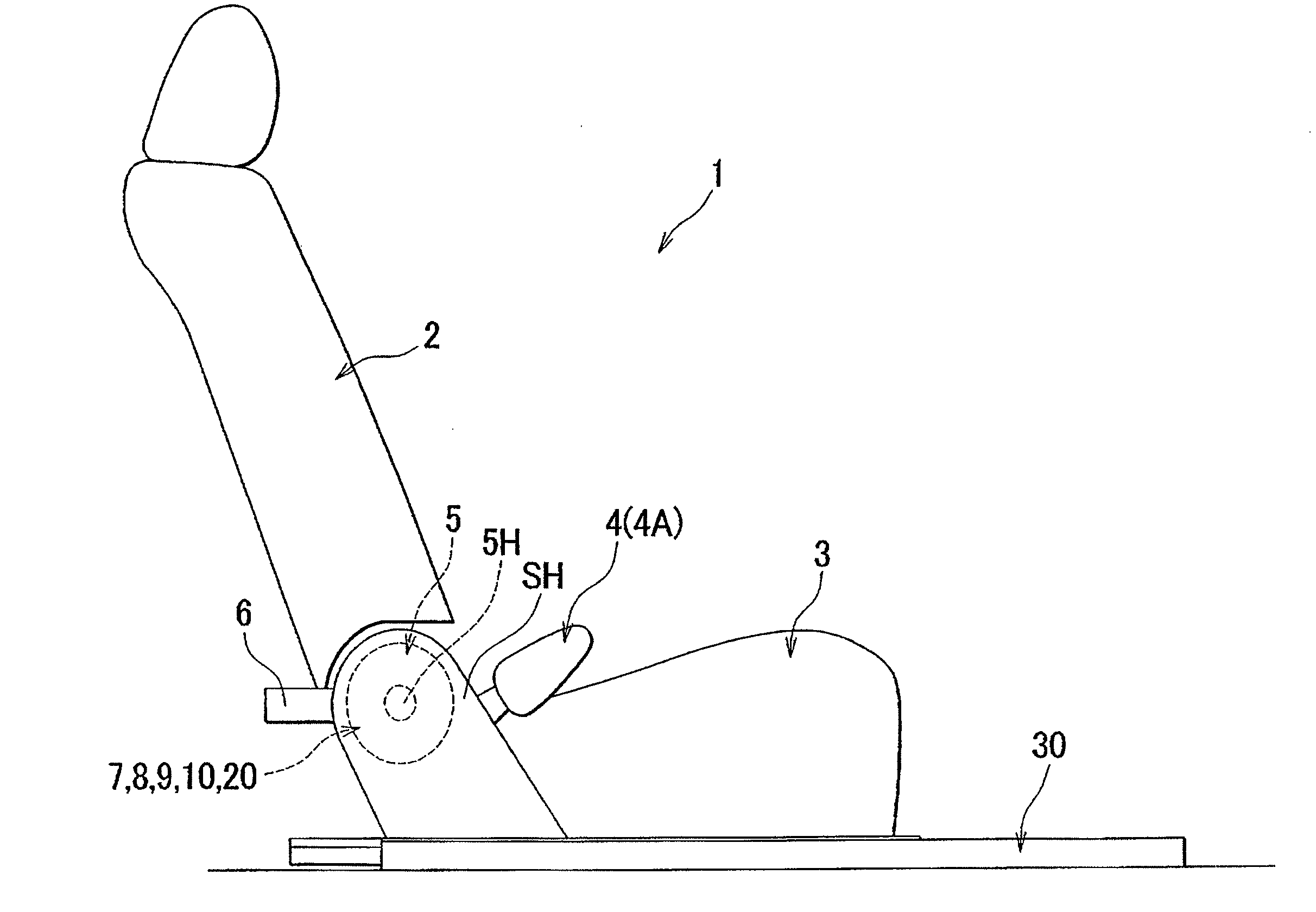
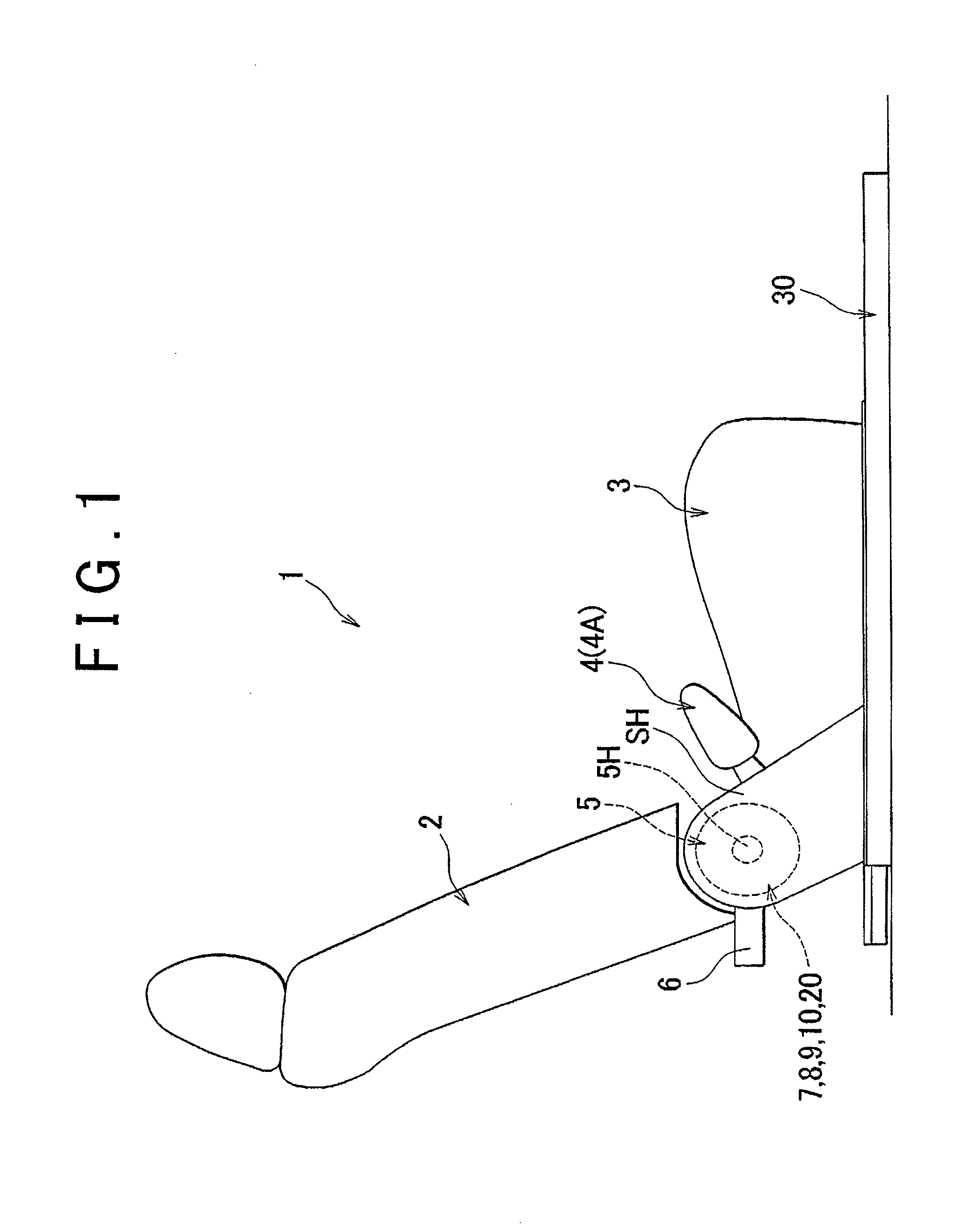
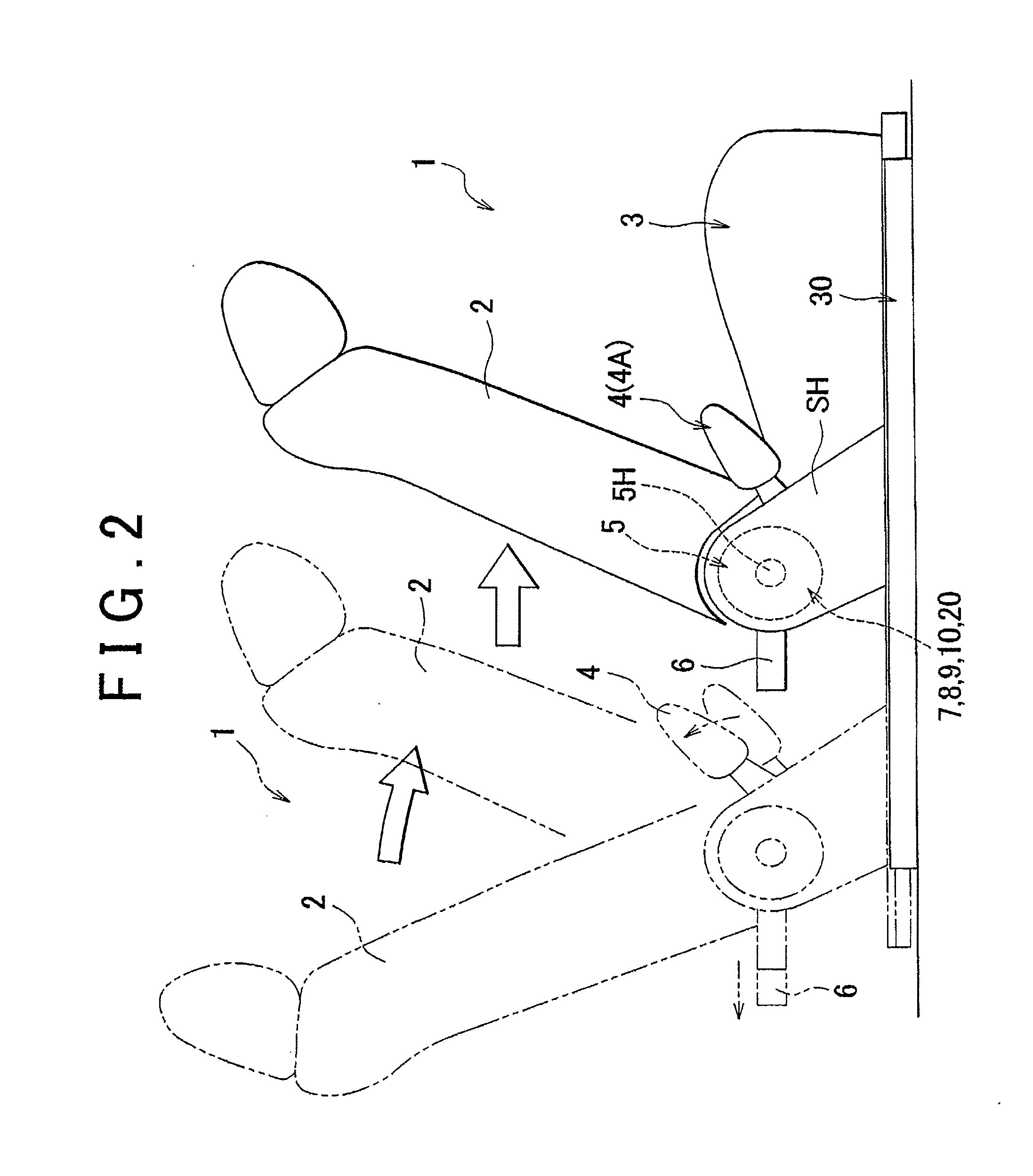
[0023]First, the structure of a vehicle seat according to an embodiment of the invention will be described with reference to FIG. 1 through FIG. 7. The vehicle seat according to the present embodiment is structured, as shown in FIG. 1, as a seat in a second row behind a driver's seat of a vehicle provided with seats arranged in three rows. A seat body 1, which is the vehicle seat according to the present embodiment, includes a seatback 2 and a seat cushion 3. The seatback 2 is constructed of a seatback frame 2F that constitutes a framework of the seatback 2, and the seatback frame 2F includes right and left side frames 2F1, 2F1. The seat cushion 3 is constructed of a seat cushion frame 3F that constitutes a framework of the seat cushion 3, and the seat cushion frame 3F includes right and left side frames 3F1, 3F1. As shown in FIG. 3, a lower end of each side frame 2F1 of the...


PUM


Abstract

A vehicle seat is provided with an operation member operated to tilt a seatback forward and disposed at such a position as to be operated from behind a seat body. The vehicle seat includes: an operation link connected at one end to the operation member and operated to be pivoted; a link mechanism that is pivotally connected to a lower end of the operation link, receives force, generated by an operation of the operation member, from the operation link to be moved, and outputs the force for cancelling fixation of a reclining angle of the seatback; and a torsion spring that is wound around a pivotally-connected portion at which the link mechanism is pivotally connected to the operation link, and biases the operation link such that the operation link is pivoted toward an initial position in which the operation link is located before being operated.

Description

INCORPORATION BY REFERENCE[0001]The disclosure of Japanese Patent Application No. 2011-111183 filed on May 18, 2011 including the specification, drawings and abstract is incorporated herein by reference in its entirety.BACKGROUND OF THE INVENTION[0002]1. Field of the Invention[0003]The invention relates to a vehicle seat. More specifically, the invention relates to a vehicle seat in which an operating member that is operated to tilt a seatback forward is fitted to a seat body such that the operating member is operated from behind the seat body.[0004]2. Description of Related Art[0005]There is a conventional vehicle seat that is structured to allow a rear-seat occupant to perform an operation for switching an operation mode to a walk-in mode in which a front seat is tilted and slid forward (hereinafter, referred to as “walk-in operation”). Japanese Patent Application Publication No. 2010-83343 (JP 2010-83343 A) describes a structure in which an operating member used to perform the wa...

Claims


Application Information

Patent Timeline
IPC IPC(8): B60N2/20B60N2/22
CPCB60N2/12
Inventor TANAKA, HIDEAKIMORIMOTO, TAKESHIHIRAMATSU, YUUICHI
Owner TOYOTA BOSHOKU KK
Learn More