Thermal test chamber

a test chamber and thermal technology, applied in the direction of vibration testing, structural/machine measurement, instruments, etc., can solve the problems of limiting the access to the components to be tested, providing unhindered access to the test object, and not providing a modular thermal chamber that can be quickly adapted to different vibration test stands, etc., to achieve rapid alteration of the set-up of the test equipment and easy mounting on the shaker test table

Active Publication Date: 2012-11-29
PICKEL MICHAEL B
View PDF8 Cites 17 Cited by
  • Summary
  • Abstract
  • Description
  • Claims
  • Application Information

AI Technical Summary

Benefits of technology

[0010]The broad purpose of the present invention is to provide an improved thermal test chamber that is readily mountable upon a shaker test table. The test chamber includes a hood having a number of non-rigid insulated side walls and a top wall which define an enclosure. A flexible two-piece bottom receives the side walls to fully enclose the test object upon the table. The two-piece bottom includes an interchangeable center piece which is sized to accommodate various tables or test objects and a collar. The collar is sized to mate with the side walls to complete the enclosure. The bottom and side walls are interconnected via hook and loop fasteners, which allows for rapid alteration of the set-up of the test equipment while maintaining a thermally sealed chamber.

Problems solved by technology

While the prior art discussed above provide some solutions to the problem of providing a thermal test chamber that can be moved to provide greater access to the test stand, they do not provide a modular thermal chamber that can be quickly adapted to different vibrational test stands and which is provides unhindered access to the test objects.
One shortcoming of the prior art and commercially available thermal test chambers is that they are formed with rigid enclosure walls, which are effective in maintaining a desired thermal chamber, but inherently limit access to the components to be tested.
Further, these test chambers are oftentimes large, expensive, fixed pieces of equipment that occupy a dedicated portion of the testing facility.

Method used


Image

  • Thermal test chamber
  • Thermal test chamber
  • Thermal test chamber

Examples


Embodiment Construction

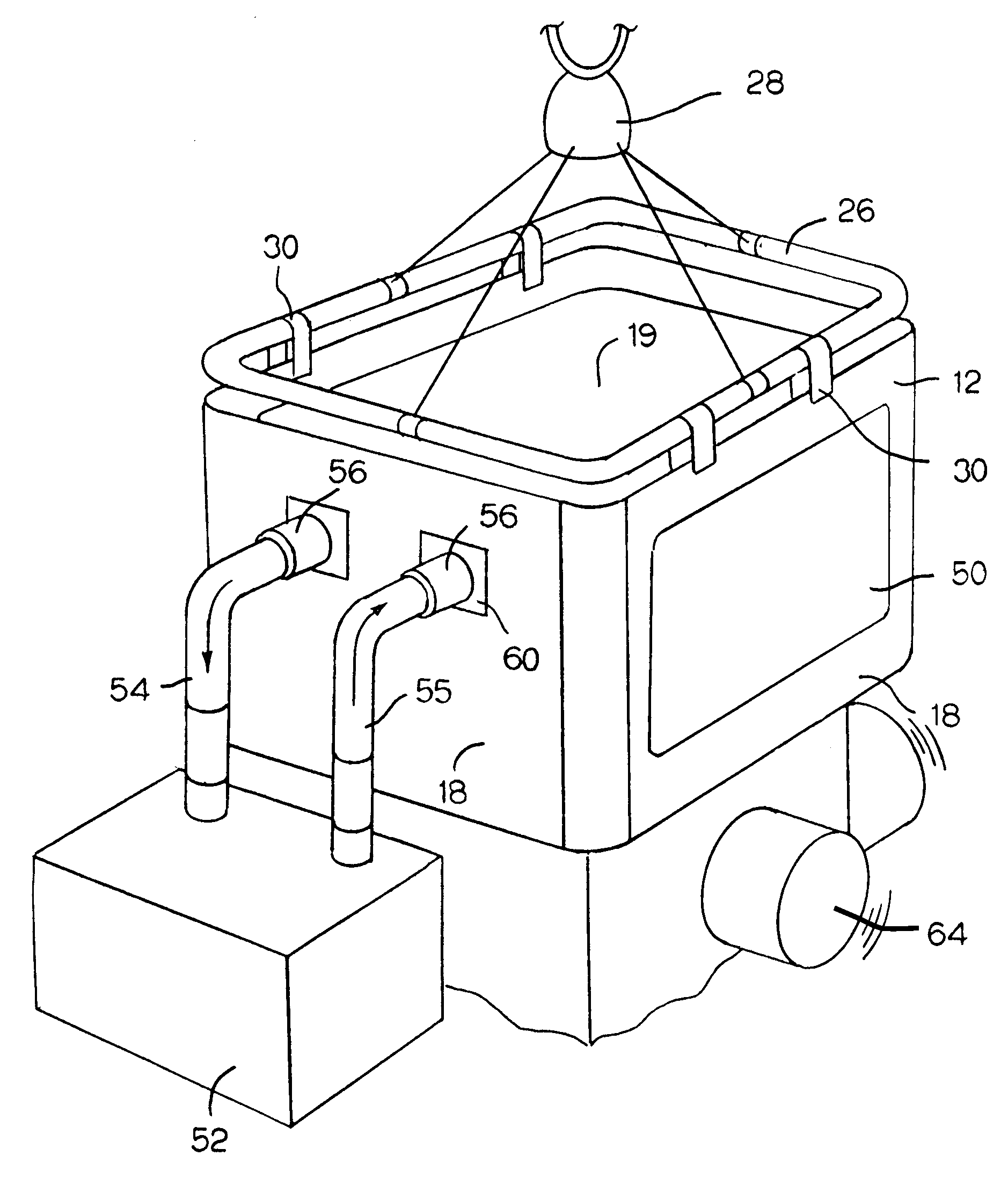
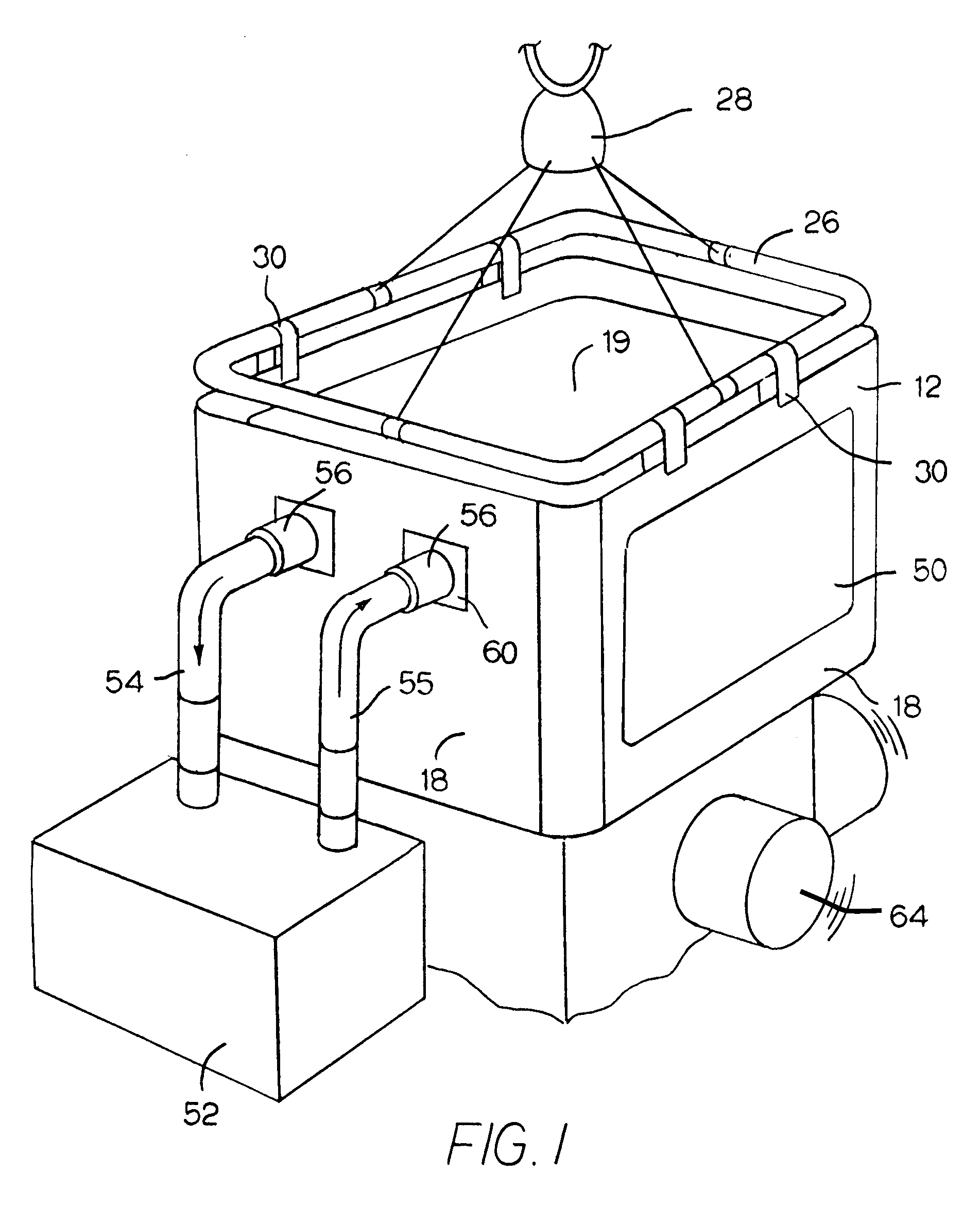
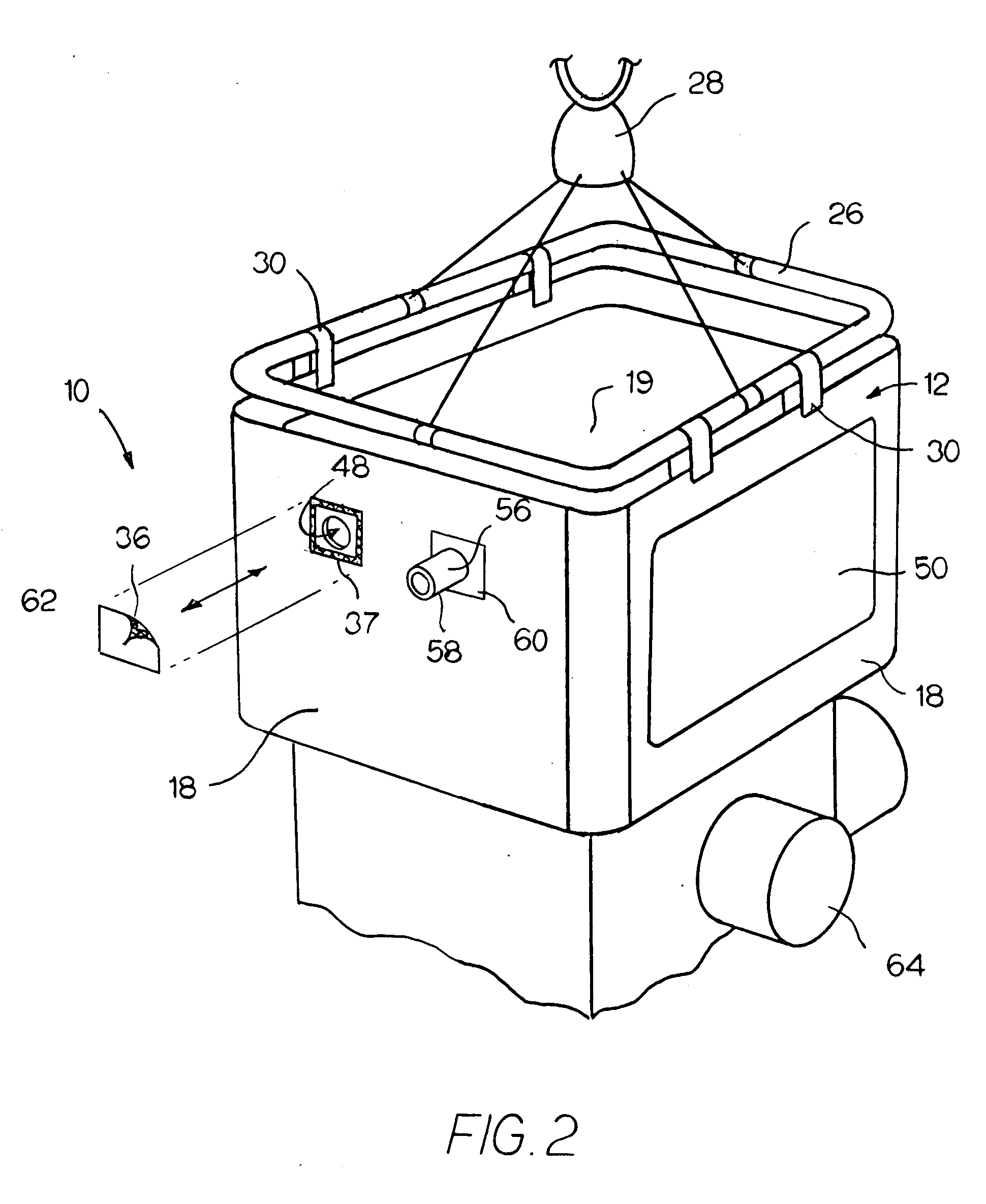
[0027]Referring now to the FIGS., a thermal test chamber 10 is shown having an enlarged enclosure or hood 12 that is removably coupled with a two-piece base 14. To ensure that the test chamber 10 is relatively light in weight and remains readily portable, the walls and panels of the entire test chamber 10 are flexible and are preferably formed from a pliable insulative textile material surrounding a middle layer of pliable insulation batting. In the preferred embodiment, the outer layer 15 and inner layer 16 are a silicone-based fabric, such as a silicone coated or impregnated canvas. The center layer 17 is a dense fibrous insulation batting, such as a blend of cotton and nylon fibers. The thermal test chamber 10, through its combination of flexible insulative layers 15-17, remains pliable at a range of operating temperatures. Further, the flexible nature of the thermal test chamber 10 reduces the burden on packaging and shipping the test chamber.

[0028]The hood 12 has a generally re...


PUM


Abstract

A soft-sided thermal test chamber that is readily mountable upon / over a shaker test table. The test chamber includes four interconnected insulated side walls and a top which define an enclosure. A two-piece bottom receives the side walls to fully enclose the test object upon the table. The two-piece bottom includes an interchangeable center piece which is sized to accommodate various tables or test objects. The side and top pieces are hung from a frame that is readily lifted using an overhead crane or chain fall hoist to allow easy access to the table during set up. The bottom and side walls are interconnected via hook and loop fasteners, which allows for rapid alteration of the set up of the test equipment while maintaining a thermally sealed chamber.

Description

FIELD OF THE INVENTION[0001]This invention is related to thermal test chambers and, more particularly, to a thermal test chambers that are adapted to transmit a vibrational input to a test object.BACKGROUND OF THE INVENTION[0002]A variety of thermal testing chambers having various enclosure configurations have been previously disclosed to enable test personnel to subject a device or devices to different temperature conditions. Oftentimes, this thermal testing is combined with shock vibration testing to help ascertain the quality and reliability of the devices.[0003]Vibration testing is conducted by mounting the device to be tested upon a table or base which is in communication with the thermal test chamber and by then vibrating the table. Some prior art examples of such thermal / vibration testing equipment may be found in the following patents.[0004]U.S. Pat. No. 6,863,123 issued to Jeng-Yau Wang discloses a metal thermal testing enclosure that is lifted up off a rigid base plate. A ...

Claims


Application Information

Patent Timeline
Patent Type & Authority Applications(United States)
IPC IPC(8): G01D21/00
CPCG01M99/002G01M7/027
Inventor PICKEL, MICHAEL B.
Owner PICKEL MICHAEL B
Why Eureka
Try Eureka