Transverse link, and method for producing a transverse link

a transverse link and transverse link technology, applied in the direction of suspensions, suspension arms, resilient suspensions, etc., can solve the problems of increasing the number of operating steps, and increasing the bending stiffness of the structure. , to achieve the effect of improving the cross section geometry, increasing the respective bending stiffness of the structure, and increasing the stiffness of the base body

Inactive Publication Date: 2012-11-29
BENTELER AUTOMOBILTECHNIK GMBH
View PDF2 Cites 7 Cited by
  • Summary
  • Abstract
  • Description
  • Claims
  • Application Information

AI Technical Summary

Benefits of technology

[0029]The presence of a dent and / or bulge has many advantages as far as production is concerned. A bulge improves the cross section geometry such that a particular high section modulus against torsion is produced. The torsional stiffness is about 1900 Nm per degree. In the case of a dent, the torsional stiffness is about 1200 Nm per degree. The presence of a dent positively affects formation of the base body, in particular the middle chamber. During forming, the presence of a dent but also of a bulge provides relieve to prevent the occurrence of stress or resultant stress tears on the top side or bottom side and to ensure that the structure is substantially stress-free after conclusion of the forming process. Furthermore, the dent or the bulge increases the respective bending stiffness of the structure.
[0030]According to another advantageous feature of the present invention, the base body may have a dent on at least an outer side. The dent may hereby be formed on the outer webs of the outer chambers. As a result, the stiffness of the base body is increased and thus of the entire transverse link, on one hand, and the bearing arms can be formed more easily because of the presence of the dent, on the other hand. The dent also reduces stress within the structure.
[0031]According to another advantageous feature of the present invention, the top side and / or the bottom side of the middle chamber can be disposed in offset arrangement to at least a top side and / or bottom side of an outer one of the hollow chambers. The offset arrangement can be realized by a lower top side and / or bottom side of the middle chamber in relation to the top side and / or bottom side of the outer chambers. This results in an additional stiffening portion and has a positive effect with respect to the section modulus of the bending.
[0032]According to another advantageous feature of the present invention, at least one outer chamber may have in cross section a rounded configuration. This also has a positive effect on the section modulus with respect to bending and / or torsion, when considering the own weight of the produced transverse link.
[0033]According to another advantageous feature of the present invention, a relieving profile can be formed in a transition zone from the base body to the bearing arms. As a result, stress cracks during the production process of a transverse link or during extended use of the transverse link are prevented. The presence of relieving profiles avoids sharp-edges transitions from base body to bearing arm so as to realize a stress diversion to thereby prevent the presence of stress cracks.

Problems solved by technology

As a result, the wheel guide links have to withstand high and intense peak loads and constant vibratory stress.
In addition, various influences during driving, for example uneven road surfaces or unbalances of one vehicle wheel, expose the wheel guide links to further substantial vibrations.
This requires a number of operating steps and cumbersome anti-corrosive measures to provide a durable and robust component (cf.
The application of welding is disadvantageous because of the change in the hardness of the microstructure and of the heat impact zone surrounding the weld sea.
In particular when geometrically complex components are involved, realization of a clean welding outcome is oftentimes difficult to attain.
Another drawback of a welded steel construction is the resultant susceptibility to corrode.
While the weld seams may enhance stiffness as a result of the coupling of various components to form a link, the addition of welding filler has the adverse effect of increasing weight.
Links made through casting are, however, disadvantageous, especially in the form of hollow components, because of the high production tolerance.
The support of cores enclosed in the castings requires in some circumstances to leave the outer side open so that the torsional stiffness of such components is adversely affected.
Another drawback of castings involves the high porosity of the component.
This reduces strength compared to structures that have been produced by a forming process.
The application of such a forging process increases production costs of the component however.

Method used


Image

  • Transverse link, and method for producing a transverse link
  • Transverse link, and method for producing a transverse link
  • Transverse link, and method for producing a transverse link

Examples


Embodiment Construction

[0041]Throughout all the figures, same or corresponding elements may generally be indicated by same reference numerals. These depicted embodiments are to be understood as illustrative of the invention and not as limiting in any way. It should also be understood that the figures are not necessarily to scale and that the embodiments are sometimes illustrated by graphic symbols, phantom lines, diagrammatic representations and fragmentary views. In certain instances, details which are not necessary for an understanding of the present invention or which render other details difficult to perceive may have been omitted.

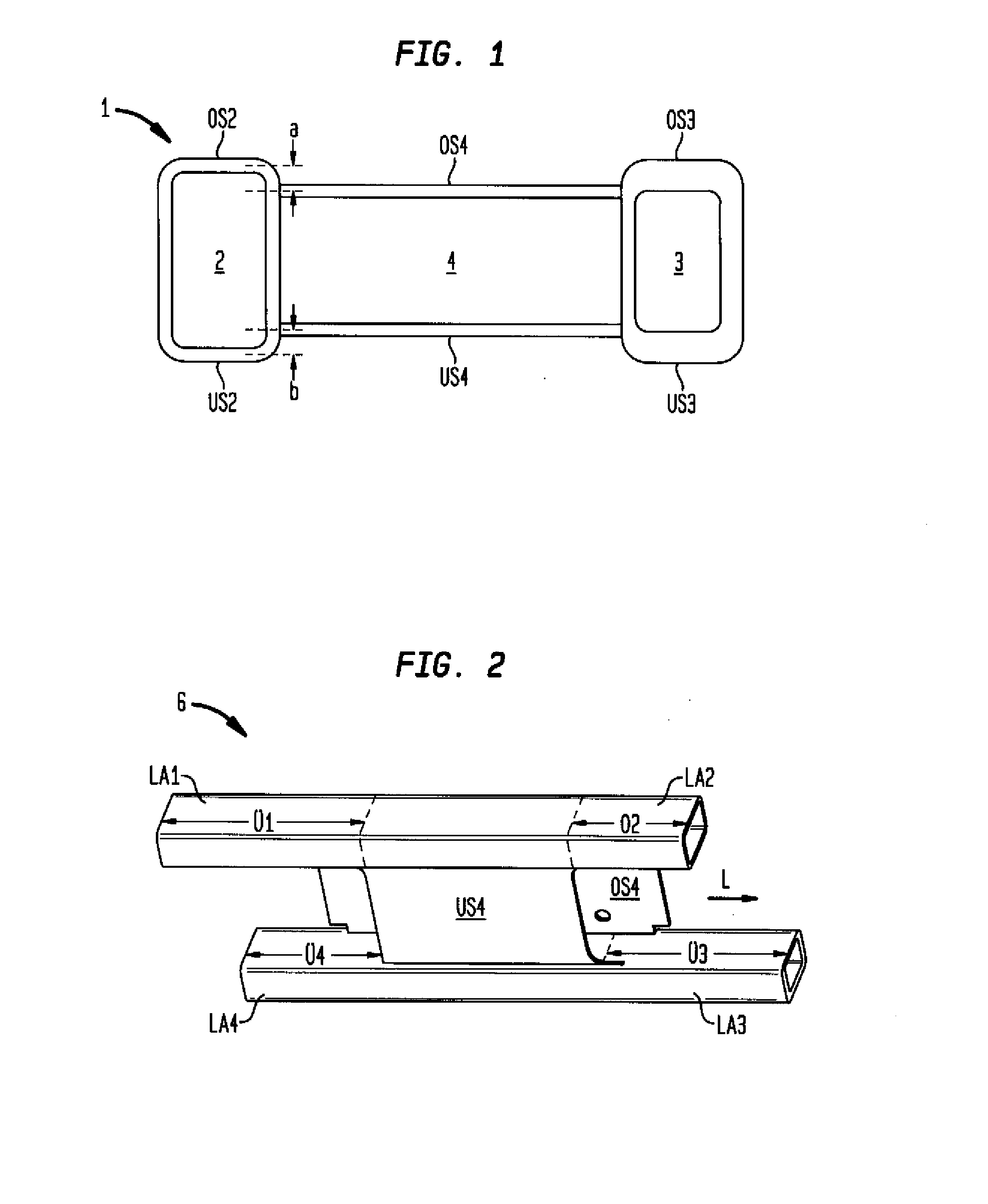
[0042]Turning now to the drawing, and in particular to FIG. 1, there is shown a cross sectional view of an extrusion profile, generally designated by reference numeral 1 and having a left outer chamber 2, a right outer chamber 3, and a middle chamber 4. The chambers 2, 3, 4 have each a top side OS2, OS3, OS4 and a bottom side US2, US3, US4. The top side OS2, OS3, OS4 and the...


PUM

PropertyMeasurementUnit
static and dynamic wheel forcesaaaaaaaaaa
vibratory stressaaaaaaaaaa
weightaaaaaaaaaa

Abstract

In a method of producing a transverse link for arrangement on a motor vehicle axle, a semifinished product is produced from an extrusion profile of light metal with at least three hollow chambers in side-by-side relationship. A top side and a bottom side of a middle one of the chambers is trimmed at ends thereof so that outer ones of the chambers form bearing arms which project beyond a base body. The middle chamber is formed with flanges which are bent and coupled with the base body. The bearing arms are bent and mounts for attachment are formed.

Description

CROSS-REFERENCES TO RELATED APPLICATIONS[0001]This application claims the priority of German Patent Application, Serial No. 10 2010 051 884.0-21, filed Nov. 22, 2010, pursuant to 35 U.S.C. 119(a)-(d), the content of which is incorporated herein by reference in its entirety as if fully set forth herein.BACKGROUND OF THE INVENTION[0002]The present invention relates to a transverse link, and to a method for producing a transverse link.[0003]The following discussion of related art is provided to assist the reader in understanding the advantages of the invention, and is not to be construed as an admission that this related art is prior art to this invention.[0004]Axle components in the form of track rods, links, or twist beams transmit static and dynamic wheel forces to an axle subframe or to a motor vehicle body. These axle components are rotatably and / or pivotally coupled between wheel carriers and vehicle-side attachment points, with the coupling normally realized via rubber-metal bea...

Claims


Application Information

Patent Timeline
Patent Type & Authority Applications(United States)
IPC IPC(8): B60G7/00B23P15/00
CPCB60G7/001B60G2206/121Y10T29/49622B60G2206/811B60G2206/82B60G2206/8103
Inventor PEDERSEN, ROALDMEYER, STEPHANRUDI, VITALISVOGLER, DIRKSOVIK, ODD PERRY
Owner BENTELER AUTOMOBILTECHNIK GMBH
Why Eureka
Try Eureka