Fiber holder and fiber laser apparatus

a fiber laser and holder technology, applied in the direction of optical elements, manufacturing tools, instruments, etc., can solve the problems of heat generation at the fiber coating etc., and it is difficult to realize a compact optical fiber holder. to achieve the effect of easily and accurately wound

Active Publication Date: 2012-11-29
ORMON CORP
View PDF21 Cites 13 Cited by
  • Summary
  • Abstract
  • Description
  • Claims
  • Application Information

AI Technical Summary

Benefits of technology

[0011]An object of the present invention is to provide a fiber holder in which an optical fiber can be wound easily and accurately, and the optical fiber can be held in a wound state.
[0021]According to the present invention, there can be realized a fiber holder by which an optical fiber can be wound easily and accurately, and also the optical fiber can be held in a wound state.

Problems solved by technology

When the rare-earth doped fiber is damaged, a laser beam leaks through the damaged portion, thereby, a problem of heat generation at the fiber, or heat generation at a fiber coating etc. may be caused.
Accordingly, it is difficult to realize a compact optical fiber holder by the bobbin disclosed in Patent Literature 1.
Moreover, it is difficult for the bobbin disclosed in Patent Literature 1 to visually confirm the state in which a fiber is wound.
However, a method for accommodating the optical fiber in the groove, i.e., a method for winding the optical fiber, is not concretely disclosed in Patent Literature 2.

Method used


Image

  • Fiber holder and fiber laser apparatus
  • Fiber holder and fiber laser apparatus
  • Fiber holder and fiber laser apparatus

Examples


Embodiment Construction

[0035]Hereinafter, an embodiment of the present invention will be described in detail with reference to the drawings. Note that, the same or corresponding portions in the drawings are denoted by the same signs, and their descriptions are not repeated.

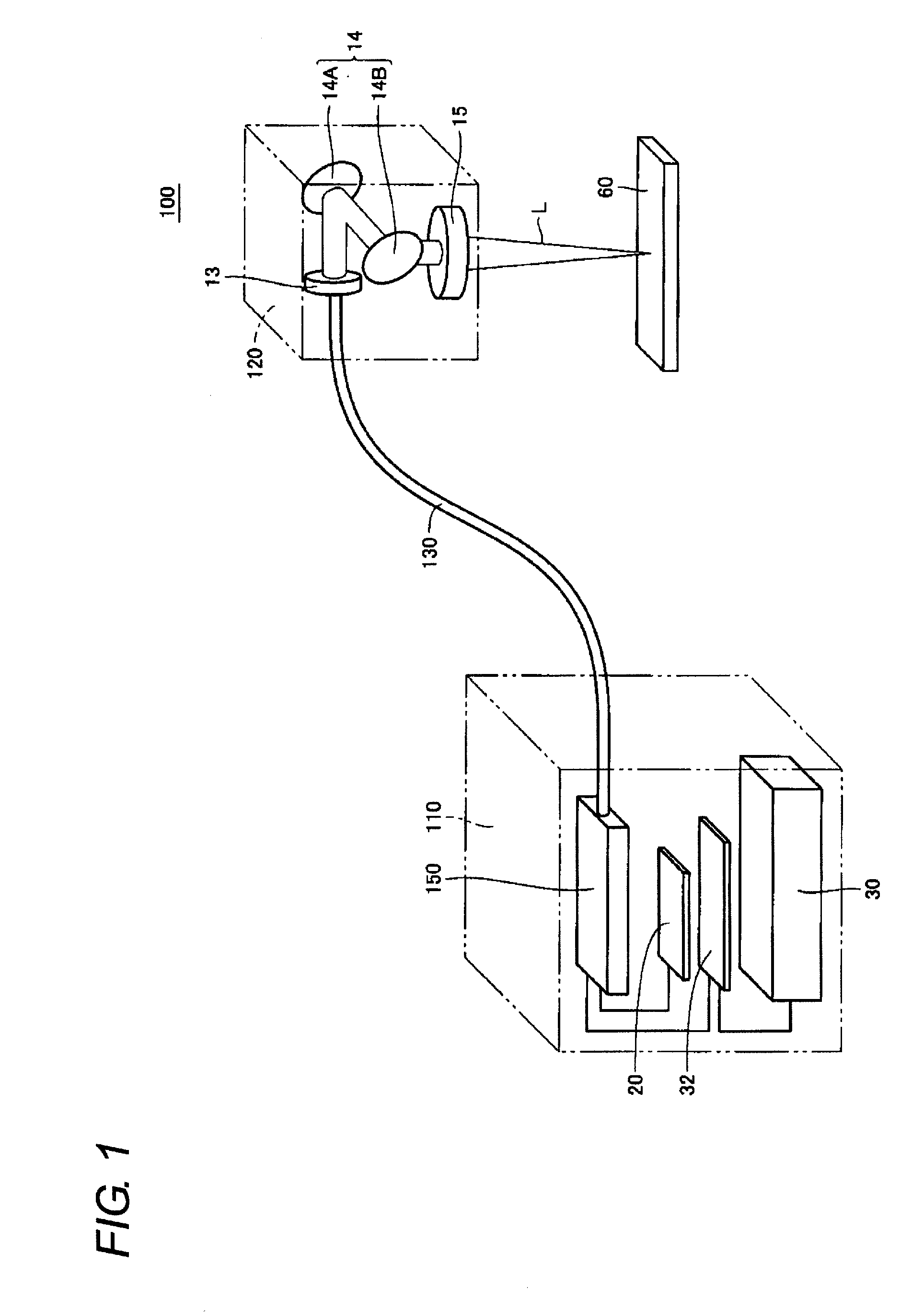
[0036]FIG. 1 is a view illustrating a schematic configuration of a laser processing apparatus according to an embodiment of the present invention. Referring to FIG. 1, the laser processing apparatus 100 is provided with a laser controller 110, a laser head portion 120, and a laser transmission portion 130 for transmitting a laser beam from the laser controller 110 to the laser head portion 120.

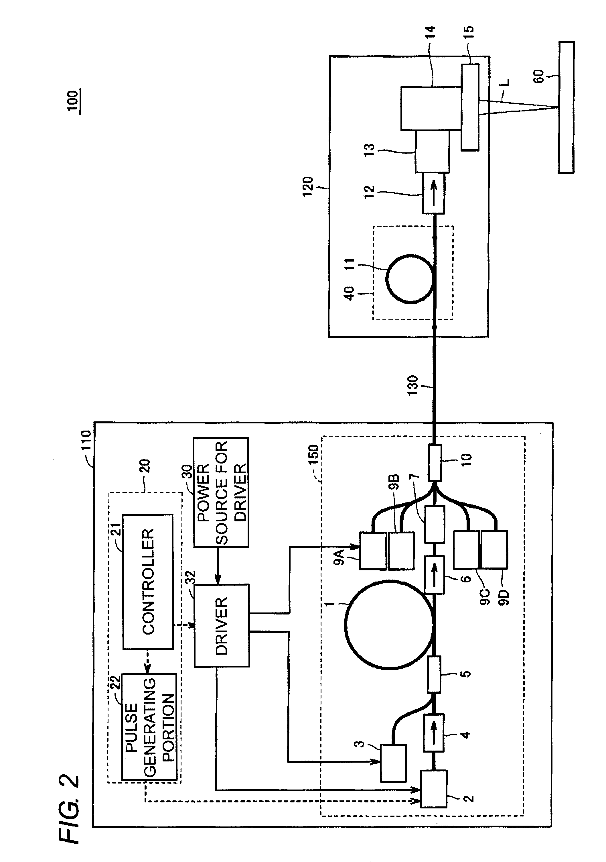
[0037]The laser controller 110 generates a laser beam and emits the generated laser beam. The laser controller 110 includes a laser oscillator 150, a control board 20, a driver 32, and a power source 30 for the driver 32. The laser oscillator 150 is driven by a driver 32 so as to perform a laser oscillation. With this, a laser beam is outputted fr...


PUM

PropertyMeasurementUnit
wavelengthaaaaaaaaaa
circumferenceaaaaaaaaaa
transparentaaaaaaaaaa

Abstract

A fiber holder which can wind an optical fiber easily and accurately, and hold an optical fiber in a wound state is provided. The optical fiber is accommodated in the groove (introduction portion) formed on the fiber bobbin, after that, the bobbin cover is rotated in the rotational direction of the helical groove while the optical fiber is kept in contact with the cutout formed in the bobbin cover. With this, the optical fiber can be accommodated in the groove. Thus, the optical fiber can be wound easily and accurately, and the optical fiber can be held on the fiber bobbin.

Description

CROSS-REFERENCE TO RELATED APPLICATION[0001]This application claims benefit of priority under 35 U.S.C. §119 to Japanese Patent Application No. 2011-118039 filed on May 26, 2011, which is expressly incorporated herein by reference in its entirety.BACKGROUND OF THE INVENTION[0002]1. Technical Field[0003]The present invention relates to a fiber holder and a fiber laser apparatus and, particularly, to a configuration of a fiber holder for winding an optical fiber and fixing the same.[0004]2. Related Art[0005]A laser processing apparatus, typically a laser marking apparatus, a welding apparatus, and a trimming apparatus, is generally configured by a laser oscillator, a driver for driving the laser oscillator, a power source for the driver, and a control board for controlling the laser. In recent years, in such a laser processing apparatus, a conventional solid state laser is progressively being replaced with a fiber laser in view of its advantages, such as a high efficiency, a high stab...

Claims


Application Information

Patent Timeline
Patent Type & Authority Applications(United States)
IPC IPC(8): G02B6/00B23K26/064G02B6/46H01S3/00H01S3/02H01S3/067
CPCH01S3/06704H01S3/06758G02B6/4457H01S3/10023H01S3/09408
Inventor NAKANO, FUMIHIKOYOKOI, TADAMASAISHIZU, YUICHIYOSHIOKA, MASAO
Owner ORMON CORP
Why Eureka
Try Eureka