Airfolw arrangement for a power tool

a power tool and airflow technology, applied in the field of angle grinders, can solve the problems of increasing the power requirements of the motor, substantial damage to the device,

Active Publication Date: 2012-11-29
BLACK & DECKER INC
View PDF23 Cites 25 Cited by
  • Summary
  • Abstract
  • Description
  • Claims
  • Application Information

AI Technical Summary

Benefits of technology

[0005]In operation, the motor assembly drives a shaft that drives both the tool assembly and the airflow generating assembly. Specifically, the motor assembly drives an active fan that creates an airstream effective to draw intake air from the ambient environment into the tool housing. Upon enter the housing, the intake air is first directed to the particle dispersion assembly. The stream of intake air enters the par...

Problems solved by technology

The particulate material, should it reach the internal operating mechanism, can cause substant...

Method used


Image

  • Airfolw arrangement for a power tool
  • Airfolw arrangement for a power tool
  • Airfolw arrangement for a power tool

Examples


Embodiment Construction

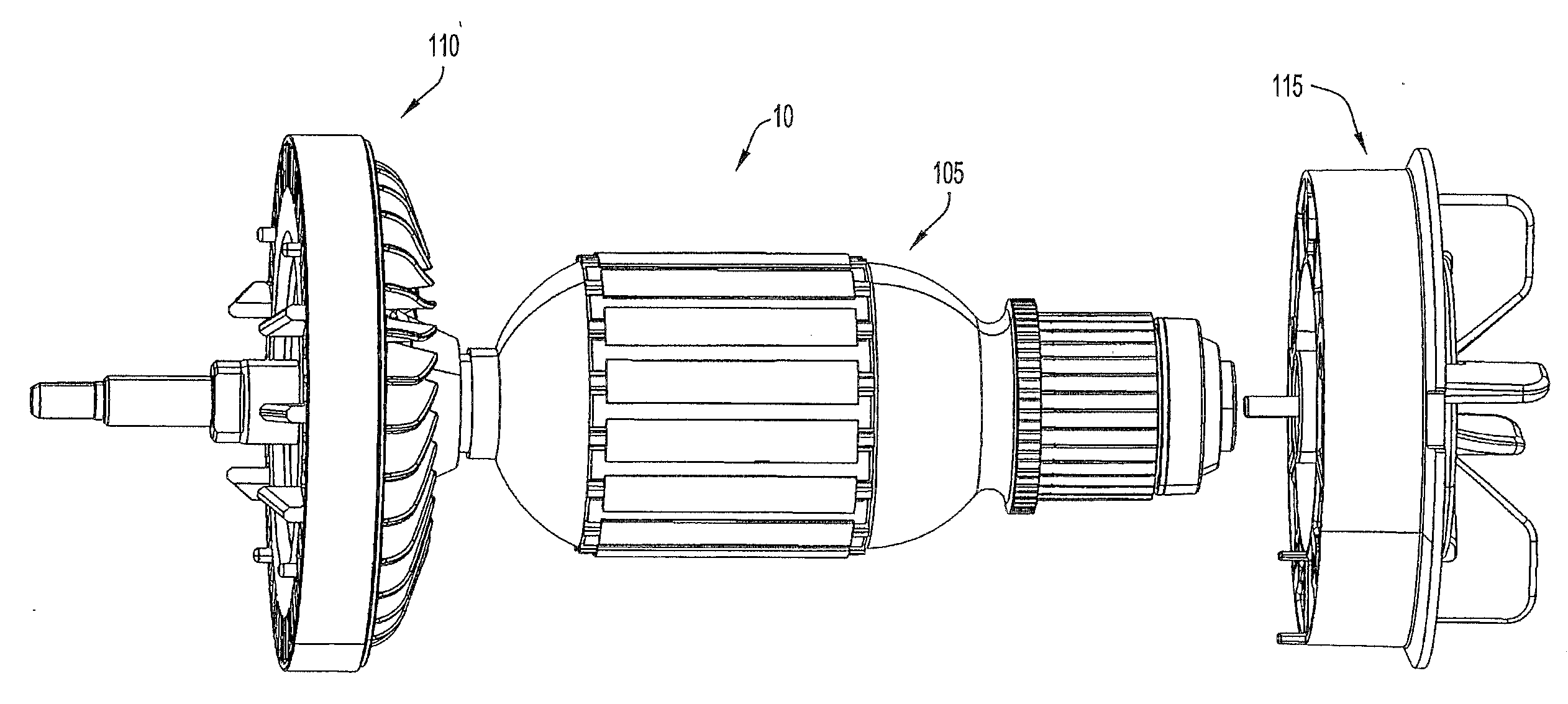
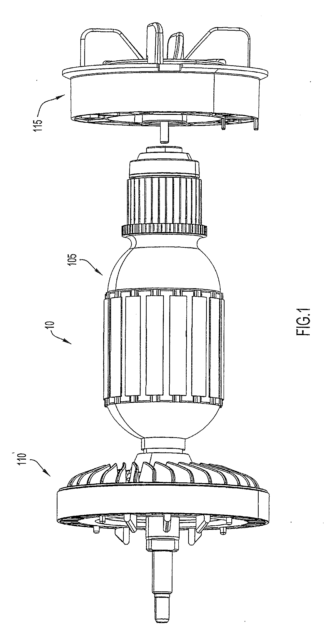
[0035]FIG. 1 illustrates an arrangement for an airflow generation and particle evacuation apparatus in accordance with an embodiment of the invention. As shown, the airflow generation and particle evacuation apparatus 10 includes a motor or armature assembly 105, an airflow generating assembly 110 (also called a cooling fan assembly), and a particle dispersion assembly 115. The assemblies 105, 110, 115 may be generally coaxial, with the airflow generation assembly 110 being disposed forward (downstream) of the motor assembly 105, and the particle assembly 115 being disposed rearward (upstream) of the motor assembly.

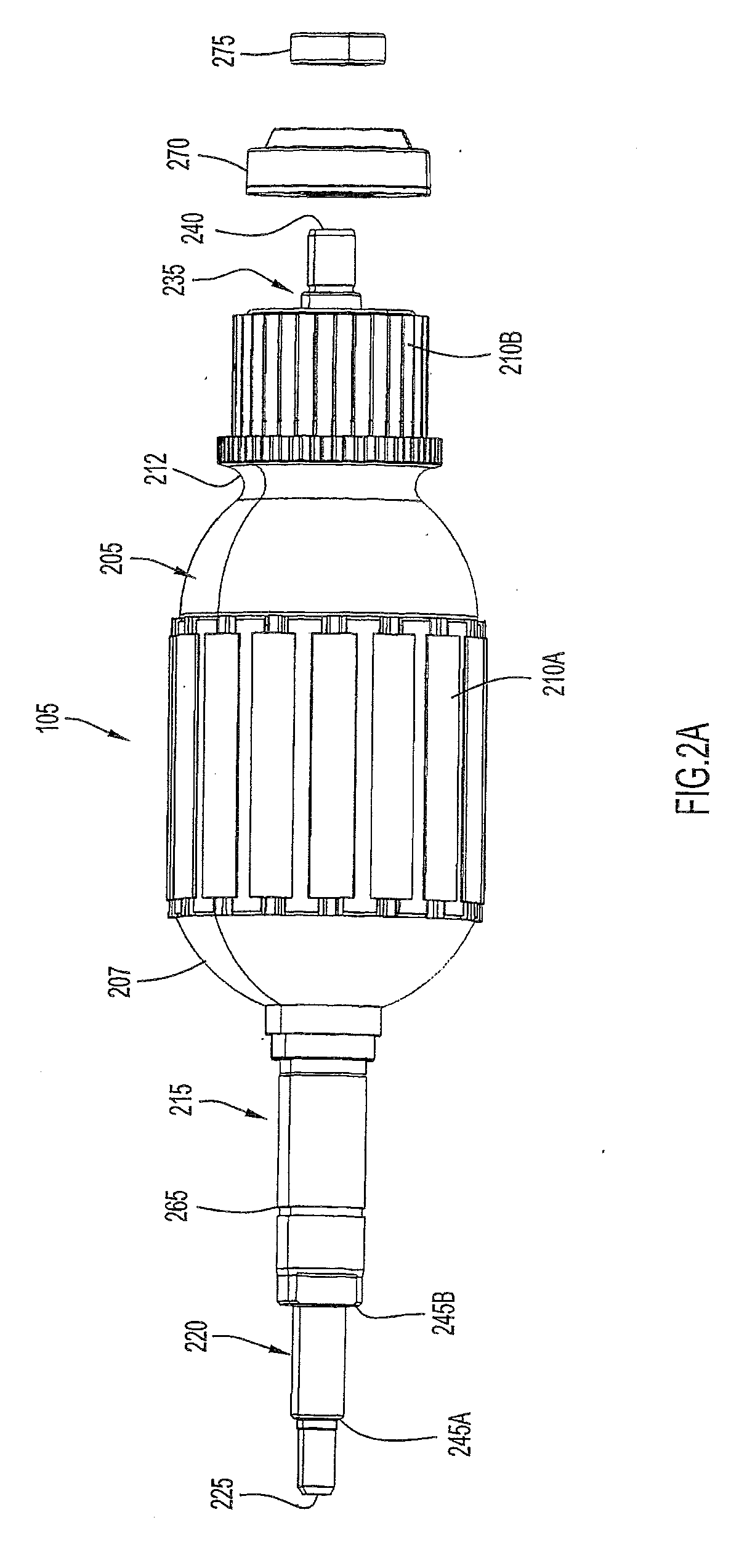
[0036]The motor assembly 105 is configured to drive the fan of airflow generating assembly 110. FIGS. 2A and 2B illustrate the motor assembly 105 in accordance with an embodiment of the present invention. The motor assembly 105 may include any type of motor suitable for its described purpose. By way of example, the motor assembly 105 may include a universal series motor. ...


PUM

PropertyMeasurementUnit
Flow rateaaaaaaaaaa
Mechanical forceaaaaaaaaaa

Abstract

The present invention is directed to an airflow generation and particle dispersion arrangement for a power tool (e.g., an angle grinder). The arrangement includes a motor, an airflow generation assembly, and a particle dispersion assembly. The airflow generation assembly includes a fan driven by the motor. When engaged, the driven fan generates an airstream that is drawn through the power tool. The particle dispersion assembly includes a passive fan that is not driven by the motor, but instead is driven by the airstream. In operation, the passive fan generates centrifugal and mechanical forces sufficient to remove particles from intake air passing through the particle dispersion assembly.

Description

FIELD OF THE INVENTION[0001]The present invention is directed toward an airflow arrangement for a power tool and, in particular, to an angle grinder including a cooling fan and a precleaner assembly with a passive fan operable to separate particulates from an intake airstream.BACKGROUND OF THE INVENTION[0002]The air intake streams of motorized devices such as vehicles, construction equipment, and powered tools often include particulate material. The particulate material, should it reach the internal operating mechanism, can cause substantial damage to the device. It is therefore beneficial to reduce the level of particulate material in the airflow at a point upstream from the operating mechanism (e.g., the motor or other equipment). Air precleaners are typically utilized to separate particulate material from the airstream. Conventional precleaners include a single motor that drives both the cooling fan and the fan of the precleaning device. This configuration not only increases the ...

Claims


Application Information

Patent Timeline
IPC IPC(8): B24B55/02
CPCB24B23/028B24B41/007H02K9/26B25F5/008H02K9/06B24B55/00
Inventor TRAUTNER, PAUL K.MILLER, PHILLIP T.GALLAGHER, WILLIAM F.DOYLE, MICHAEL C.
Owner BLACK & DECKER INC
Why Eureka
Try Eureka