

Image forming apparatus and method of discharging recording liquid
a technology of image forming apparatus and liquid discharge, which is applied in printing and other directions, can solve the problems of contaminating the recording face of paper, reducing and affecting the ejection performance of the recording head
- Summary
- Abstract
- Description
- Claims
- Application Information
AI Technical Summary
Benefits of technology
Problems solved by technology
Method used
Image

Examples
configuration example 1
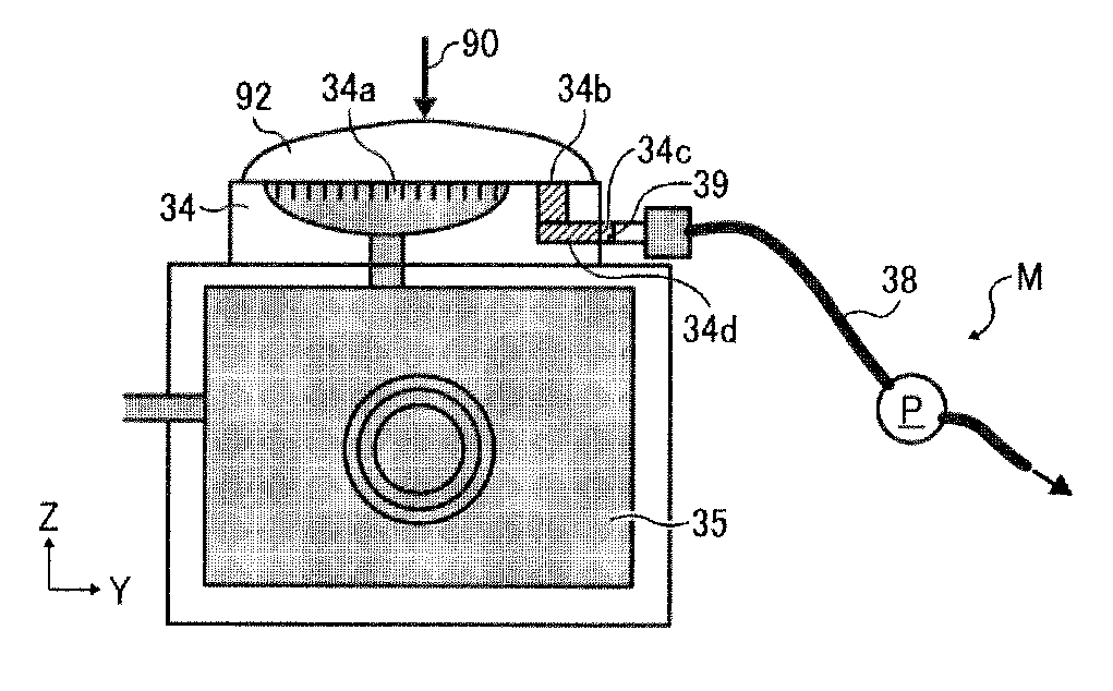
[0069]FIG. 7 shows a first configuration example of the maintenance-and-recovery mechanism of the image forming apparatus according to this exemplary embodiment.
[0070]For the image forming apparatus according to this exemplary embodiment, as illustrated in FIG. 7, the recording head 34 (nozzles 34a) is oriented upward so that ink stored in the head tank 35 is ejected vertically upward from the nozzles 34a. For such a configuration, if bubbles enter the nozzles 34a and cause ejection failure, as illustrated in FIG. 7, a first suction pump separately provided from a second suction pump P illustrated in FIG. 7 sucks ink upward from the recording head 34 in a state in which the suction cap 92 (also referred to as simply “cap”) is brought into contact with the nozzle face of the recording head 34 (a face from which ink is ejected) by pressure of a pressing unit 90. After the suction, the suction cap 92 is separated from the recording head 34 (decapping). At this time, residual ink in the...
configuration example 2
[0073]FIG. 8 shows a second configuration example of the maintenance-and-recovery mechanism of the image forming apparatus according to this exemplary embodiment.
[0074]The above-described configuration example 1 illustrated in FIG. 7 may be disadvantageous in the performance of discharging waste liquid during decapping. Hence, for this configuration example 2, as illustrated in FIG. 8, a suction unit (e.g., a suction pump P) is connected to a suction cap 92 (and a suction pump is not provided at a waste-liquid tube 38). After head suction is finished, the direction in which air flows is reversed to release air to the atmosphere. Thus, air is sent into the suction cap 92, thus facilitating waste-liquid discharge.
[0075]For example, in FIG. 8, during head suction, the suction unit (e.g., the suction pump P) sucks bubbles from nozzles 34a and further sucks the bubbles upward. In other words, bubbles (in ink) sucked from the nozzles are further sucked upward (toward the suction unit). Af...
configuration example 3
[0077]FIG. 9 shows a third configuration example of the maintenance-and-recovery mechanism of the image forming apparatus according to this exemplary embodiment.
[0078]For this configuration example 3, as illustrated in FIG. 9, an air release valve 97 is connected to the suction cap 92 in the configuration of FIG. 7, thus obtaining effects equivalent to the above-described effects. The air release valve 97 is disposed at a position opposing the waste liquid port 34b (the hole at the nozzle face) in a direction indicated by an arrow Z in FIG. 9. As with the above-described configuration example 2, after head suction is finished, the air release valve 97 feeds air into the suction cap 92 (toward the nozzle face in the suction cap 92). The air release valve 97 is dedicated for the air feed operation (and does not perform sucking operation). As a result, ink in the suction cap 92 (ink on the nozzle face) is pushed by air flowing into the suction cap 92 to flow toward the waste liquid por...
PUM
 Abstract
Description
Claims
Application Information