Zoom Lens System, Imaging Device and Camera
a zoom lens and imaging device technology, applied in the field of zoom lens systems, imaging devices, and cameras, can solve the problems of unsatisfactory digital requirements, unsuitable lens unit arrangement, etc., and achieve the effects of high resolution, reduced thickness, and high zooming ratio
- Summary
- Abstract
- Description
- Claims
- Application Information
AI Technical Summary
Benefits of technology
Problems solved by technology
Method used
Image

Examples
embodiments 1 to 8
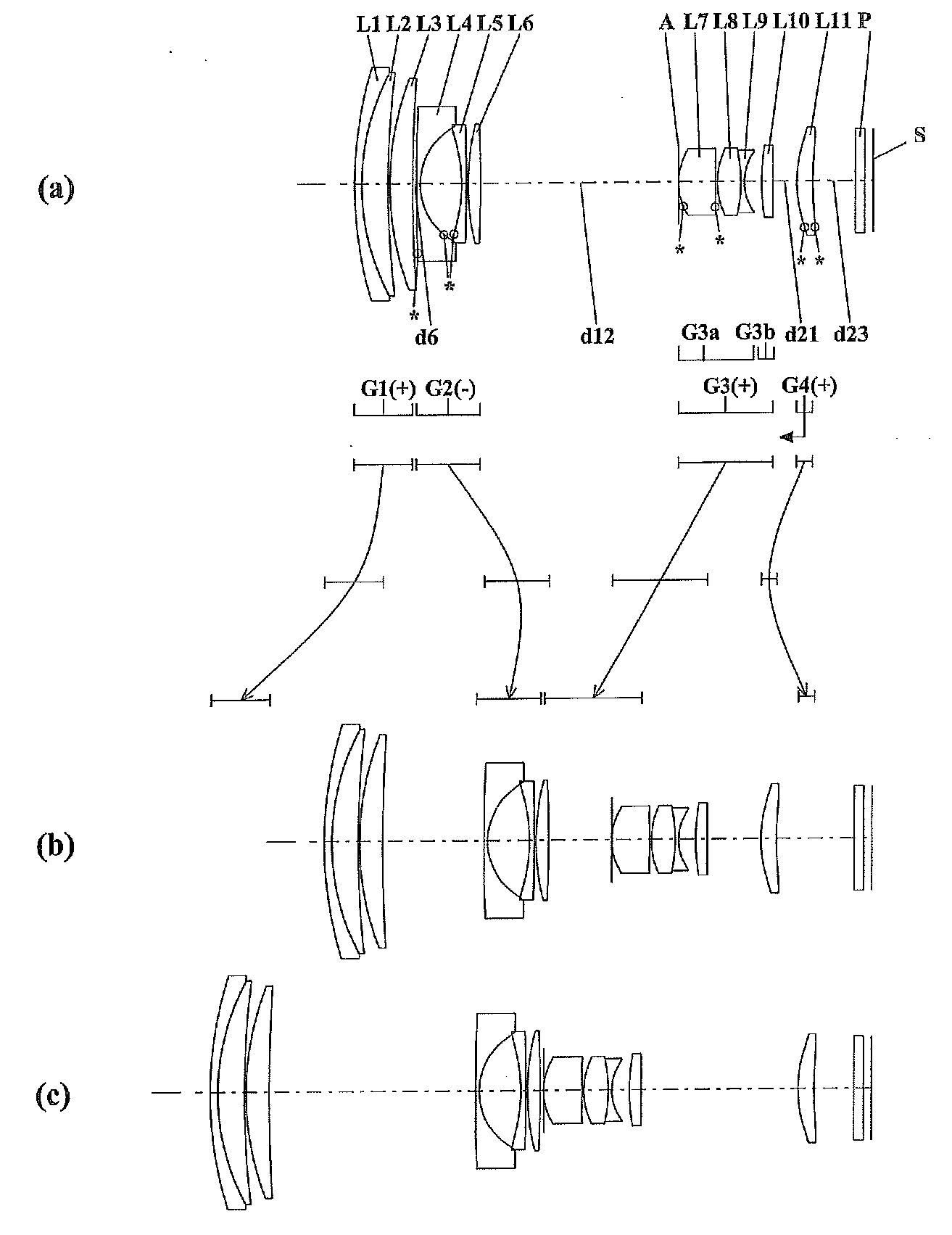
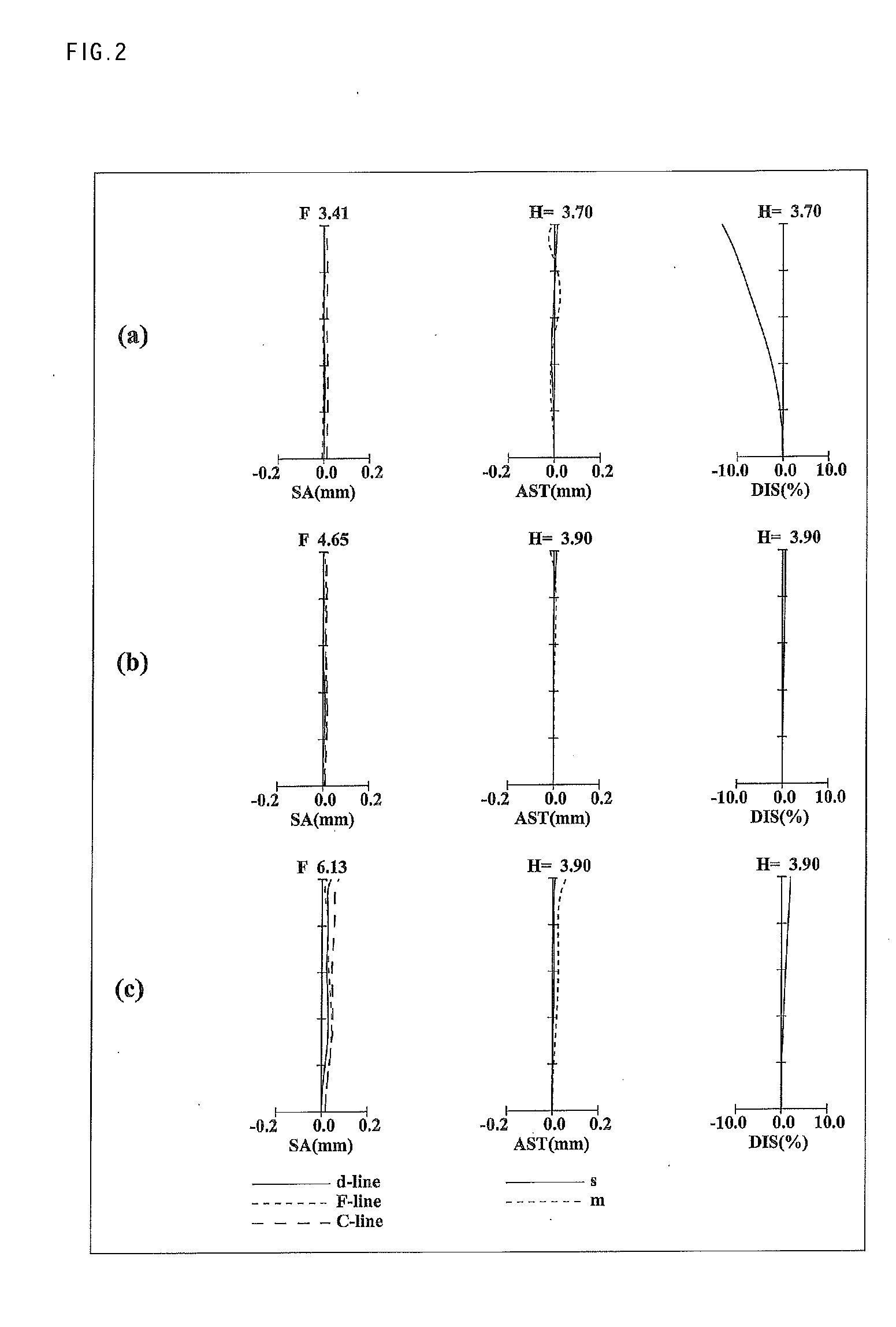
[0086]FIGS. 1, 4, 7, 10, 13, 16, 19 and 22 are lens arrangement diagrams of zoom lens systems according to Embodiments 1 to 8, respectively.
[0087]Each of FIGS. 1, 4, 7, 10, 13, 16, 19 and 22 shows a zoom lens system in an infinity in-focus condition. In each Fig., part (a) shows a lens configuration at a wide-angle limit (in the minimum focal length condition: focal length fW), part (b) shows a lens configuration at a middle position (in an intermediate focal length condition: focal length fM=√(fW*fT)), and part (c) shows a lens configuration at a telephoto limit (in the maximum focal length condition: focal length fT). Further, in each Fig., an arrow of a straight or curved line provided between part (a) and part (b) indicates the movement of each lens unit from a wide-angle limit through a middle position to a telephoto limit. Furthermore, in each Fig., an arrow imparted to a lens unit indicates focusing from an infinity in-focus condition to a close-object in-focus condition. Tha...
embodiment 1
[0092]As shown in FIG. 1, the first lens unit G1, in order from the object side to the image side, comprises: a negative meniscus first lens element L1 with the convex surface facing the object side; a positive meniscus second lens element L2 with the convex surface facing the object side; and a positive meniscus third lens element L3 with the convex surface facing the object side. Among these, the first lens element L1 and the second lens element L2 are cemented with each other. In the surface data of the corresponding Numerical Example described later, surface number 2 is imparted to an adhesive layer between the first lens element L1 and the second lens element L2.
[0093]The second lens unit G2, in order from the object side to the image side, comprises: a negative meniscus fourth lens element L4 with the convex surface facing the object side; a negative meniscus fifth lens element L5 with the convex surface facing the image side; and a bi-convex sixth lens element L6. Among these...
embodiment 2
[0099]As shown in FIG. 4, the first lens unit G1, in order from the object side to the image side, comprises: a negative meniscus first lens element L1 with the convex surface facing the object side; and a bi-convex second lens element L2. The first lens element L1 and the second lens element L2 are cemented with each other. In the surface data of the corresponding Numerical Example described later, surface number 2 is imparted to an adhesive layer between the first lens element L1 and the second lens element L2. Further, the second lens element L2 has an aspheric image side surface.
[0100]The second lens unit G2, in order from the object side to the image side, comprises: a negative meniscus third lens element L3 with the convex surface facing the object side; a negative meniscus fourth lens element L4 with the convex surface facing the image side; and a bi-convex fifth lens element L5. Among these, the third lens element L3 has two aspheric surfaces. The fourth lens element L4 has ...
PUM
 Abstract
Description
Claims
Application Information