LED lampholder and lamp system with means to prevent lamping of nonconforming lamps

a technology of non-conformity and lamp holders, which is applied in the direction of semiconductor devices for light sources, coupling device connections, lighting and heating apparatus, etc., can solve the problems of indirect coupling, posing a danger, and the lamp holders still may not be suitable for receiving certain types of led lamps, so as to prevent improper coupling

Inactive Publication Date: 2012-12-06
LEVITON MFG
View PDF3 Cites 89 Cited by
  • Summary
  • Abstract
  • Description
  • Claims
  • Application Information

AI Technical Summary

Benefits of technology

[0014]The present disclosure is directed to a lampholder assembly which includes a first and second lampholder. The first lampholder includes a first electrical connector adapted and configured to couple and electrically connect a first end of an LED lamp to a voltage supply-line of a host electrical system. The second electrical connector is adapted and configured to couple and electrically connect the first end of the LED lamp to a neutral return-line of the host electrical system and to prevent improper coupling to the voltage supply-line.

Problems solved by technology

Installation of a fluorescent lamp in a fluorescent lampholder that has been rewired to accept self-ballasted LED lamps would result in direct coupling of the fluorescent lamp to the branch circuitry, without the required ballast, posing a danger, to the host electrical system, the host structure, a person nearby, the lampholder, and / or the lamp.
In addition, once a fluorescent lampholder has been rewired to receive an LED lamp, the lampholder still may not be suitable to receive certain types of LED lamps.
First, many LED lamps are considerably heavier than fluorescent lamps, sometimes three times heavier.
A standard fluorescent lampholder may not be designed to hold the weight of an LED lamp.
The danger of the lampholder's insufficient weight capacity increases when the lampholder is subject to vibrations or impact, such as when mounted below a ceiling that is subject to vibrations from above, e.g., foot or moving vehicle traffic, or to impact from below, e.g., from an object, such as a ball.
Additional dangers exist due to the different construction of the fluorescent and LED lamps.
An LED lamp supported by a lampholder that is not designed to compensate for a change in fluorescent lamp length may either drop out of the lampholder due to lamp contraction, or break while installed in the lampholder due to lamp expansion.
When the retrofit includes rewiring of the lampholder connections, it may create an unknown hazard that could include the danger of electric shock or fire.
This can create an unknown hazard, because markings or labels that indicate that the lampholder includes an internal shunt may or may not be provided on the back of the lampholder and, if provided, may not be visible once the lampholder is installed.
If a fixture is rewired as part of an LED retrofit, and the line and neutral connections are brought to the terminals of an internally shunted lampholder, a short-circuit across the branch circuit conductors may result, posing a severe potential hazard.
A further danger exists when the internal contacts of a fluorescent lampholder are configured to be coupled to a supply voltage-line and a return neutral-line, respectively.
If these two lines are spaced physically too closely together, arcing may result, posing a danger of shock or fire.
However, once the first end of the lamp is coupled to the supply voltage-line, the other end of the lamp may become electrically live and pose a serious danger to the person installing the lamp, as they can easily come in contact with the exposed electrically live component.

Method used


Image

  • LED lampholder and lamp system with means to prevent lamping of nonconforming lamps
  • LED lampholder and lamp system with means to prevent lamping of nonconforming lamps
  • LED lampholder and lamp system with means to prevent lamping of nonconforming lamps

Examples


second embodiment

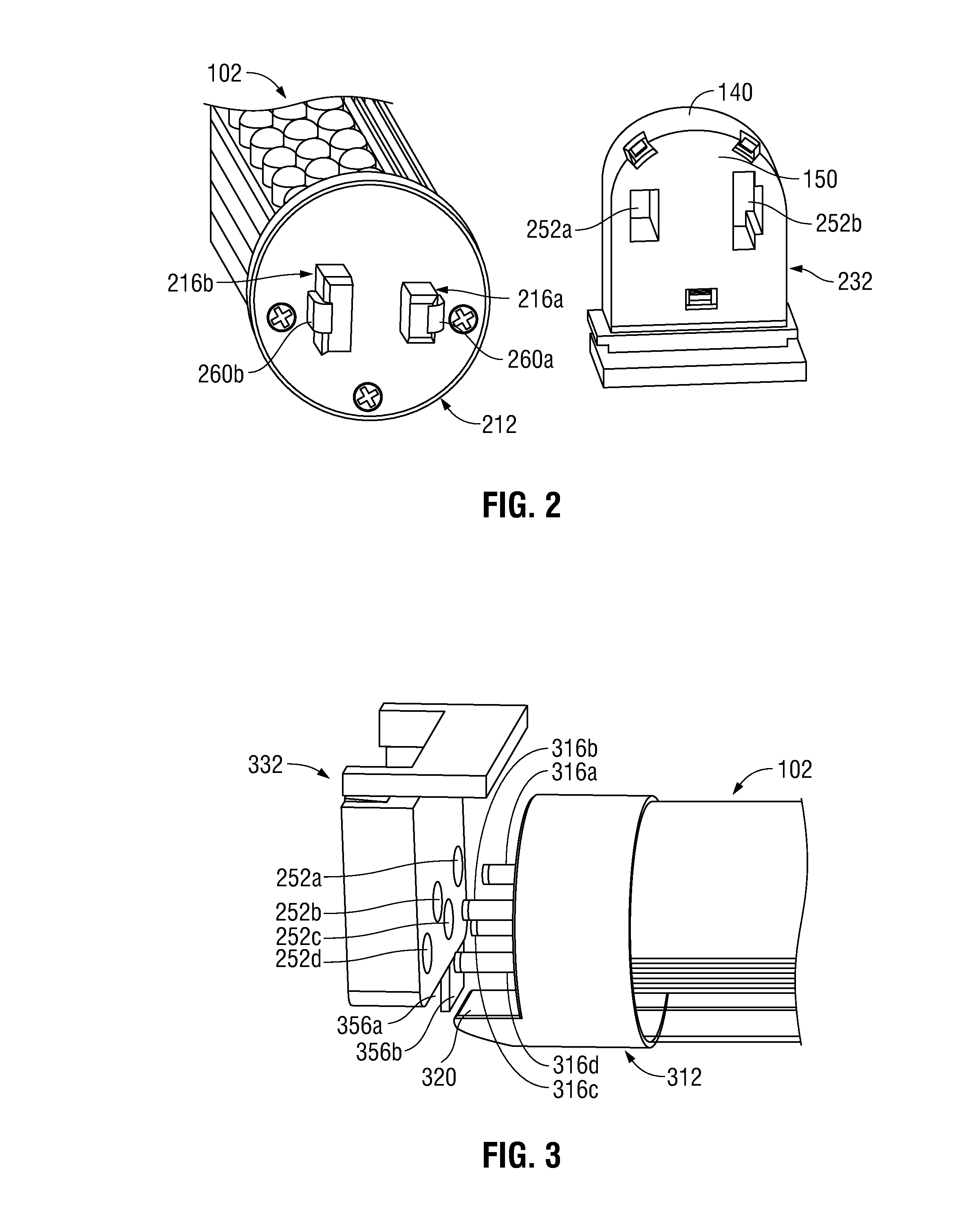
[0040]With reference to FIG. 2, a first end 212 of lamp 102 and a first lampholder 232 of LED lamp assembly 100 is shown. First end 212 of lamp 102 and first lampholder 232 are embodiments of the first end 112 of lamp 102 and the first lampholder 132 shown in FIG. 1, respectively. First end 212 is provided with a pair of male electrical connectors 216a and 216b. Each electrical connector 216a, 216b includes a conductor formed of a conductive material that electrically couples to the electrical assembly 108 and is further exposed for electrically coupling to another electrical conductor. Furthermore, each electrical connector 216a, 216b may include a resilient member 260a and 260b.

[0041]First lampholder 232 includes a pair of female electrical connectors 252a and 252b formed as apertures that are sized and shaped, respectively, to receive connectors 216a and 216b. Connectors 252a and 252b are each provided with an internal electrical conductor (not shown). One internal electrical co...

third embodiment

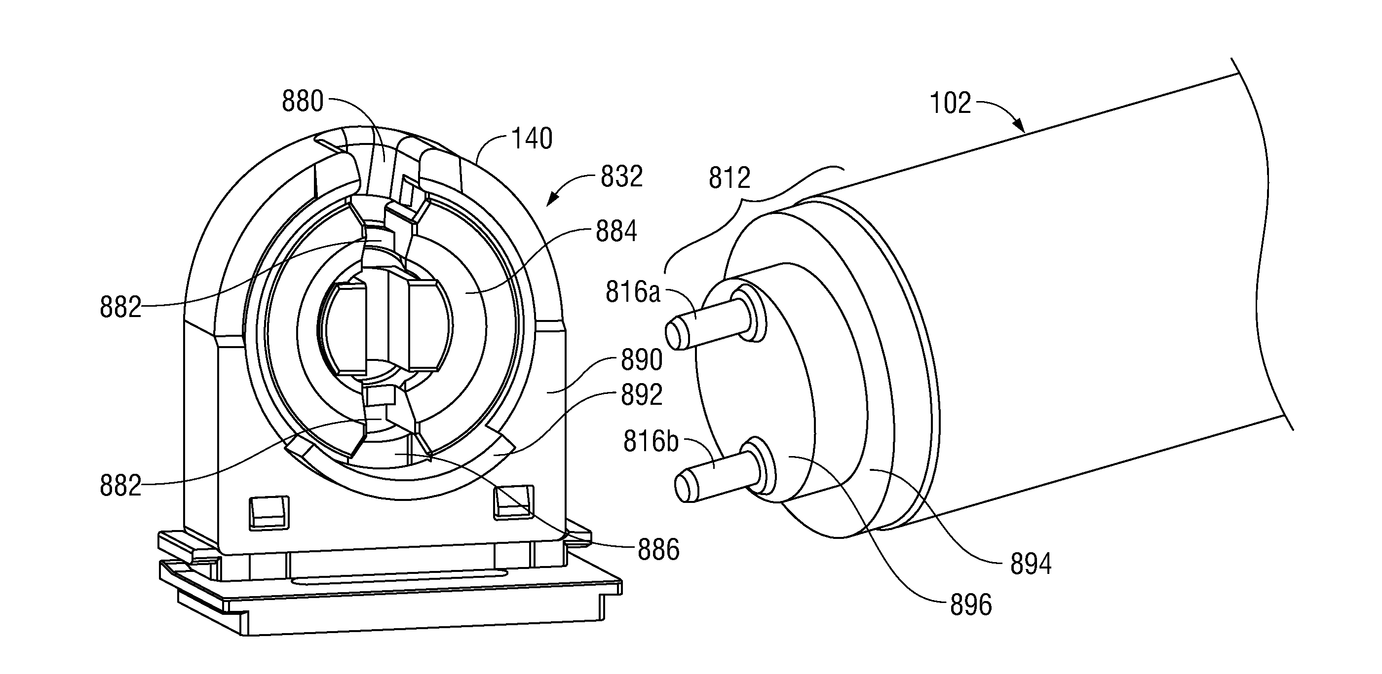
[0044]FIGS. 3 and 4 show a first end 312 of lamp 102 and a first lampholder 332 of LED lamp assembly 100. First end 312 of lamp 102 and first lampholder 332 are embodiments of the first end 112 of lamp 102 and the first lampholder 132 shown in FIG. 1, respectively. First end 312 is provided with a plurality of at least three electrical connectors 316a-316d that are shaped as elongated pins. While four connectors 316a-316d shaped as pins are illustrated, the disclosure is not limited to four connectors or to a pin shape. Any number of two or more connectors is envisioned, and the connectors may be shaped or packaged in a variety of ways, such as differently dimensioned pins, flat contacts, bump-out contacts, etc.

[0045]The connectors 316a-316d are received by connectors 352a-352d, respectively, which are formed as apertures provided in first lampholder 332. Connectors 352a-352d are sized, shaped and positioned for receiving or mating with connectors 316a-316d. Furthermore, each connec...

first embodiment

[0053]FIGS. 5-6 show a plunger arrangement in which second end 514 is provided with an extending plunging member 570 that is received and held securely by second lampholder 534. A biasing force produced by springs provided within the second lampholder 534 provides the secure hold. Second end 514 of LED lamp 102 has a front face 571 that faces the second lampholder 534. Plunger member 570 extends from the front face 571. Second lampholder 534 has a movable annular member 576 that has a front face 573 and opposing back face 575. When installing LED lamp 102, front face 573 faces front face 571 of the second end 514 of the LED lamp 102. Front face 573 is provided with at least one opening 572 defined by the annular member 576 for receiving plunger member 570. Behind annular member 576 are one or more springs 574. The springs 574 are mounted within second lampholder 534, e.g., to an inner face of a back wall of second lampholder 534. A front end of the springs 574 physically contacts th...


PUM


Abstract

A lampholder assembly is provided which includes first and second lampholders. The first lampholder includes first and second electrical connectors for electrically connecting a first end of an LED lamp to a host voltage supply-line and neutral-line, respectively, and preventing improper coupling to the voltage supply-line. The second lampholder includes a first plunger component for coupling to a second end of the LED lamp and cooperating with a second plunger component provided on the second end of the LED lamp for biasing at least one of the first and second plunger components to generate a force for supporting the LED lamp in an installation position. The first lampholder engages the LED lamp only when the LED lamp is oriented in the installation position so that the first and second electrical connectors electrically connect the LED lamp to the voltage supply-line and neutral return-line, respectively, for operating the LED lamp.

Description

BACKGROUND[0001]1. Technical Field[0002]The present disclosure relates generally to a system and method for preventing installation of a fluorescent lamp in a lampholder that is intended to receive an LED lamp. In particular, the present disclosure relates to a system and method for ensuring proper and safe installation of an LED lamp in an LED lampholder while preventing improper installation of a fluorescent lamp in the LED lampholder.[0003]2. Description of Related Art[0004]LED lamps are becoming more popular due to their advantages over lamps using other lighting technologies. LED lamps excel in energy consumption efficiency, reliability, and length of lifetime. Additional advantages of LED lamps, when compared specifically to fluorescent lamps, include: the lamp has the ability to turn on instantly; the lamp's lifetime is unaffected by cycling on and off, such as when powered on and off during normal usage; the lamp's electrical components are securely mounted and are thus more...

Claims


Application Information

Patent Timeline
Patent Type & Authority Applications(United States)
IPC IPC(8): H01R33/00H01R13/625
CPCH01R13/7175H01R33/0845F21V19/008F21K9/175F21V25/04F21K9/272
Inventor SCHAPIRA, FRANCISCOGALLUCCIO, GREGORYTUFANO, ANTHONYSALAZAR, CARLOSSARINO, RUELQUERCIA, ROBERT
Owner LEVITON MFG
Why Eureka
Try Eureka