Connector coupling structure and holder device

Inactive Publication Date: 2012-12-06
AISIN AW CO LTD +1
View PDF10 Cites 5 Cited by
  • Summary
  • Abstract
  • Description
  • Claims
  • Application Information

AI Technical Summary

Benefits of technology

[0008]In addition, the connector body can shift with respect to the holder body within a range that the second connector can follow the first connector. Therefore, after the connectors are connected, even if the electronic device becomes misaligned with respect to the holder body and the first connector is shifted with respect to the holder body, the second connector shifts with respect to the holder body so as to follow the first connector. Accordingly, an unnecessary force acting between the connector terminal of the first connector and the connector terminal of the second connector can be suppressed.
[0011]The shift amount that the second connector can be shifted with respect to the reference position is set larger than the shift amount that the first connector can be shifted with respect to the reference position. Therefore, after the connectors are connected, even if the electronic device becomes misaligned with respect to the holder body and the first connector is shifted with respect to the reference position, the second connector shifts with respect to the holder body so as to follow the first connector. Accordingly, an unnecessary force acting between the connector terminal of the first connector and the connector terminal of the second connector can be suppressed.
[0015]According to the constitution described above, a constitution in which the connector body is shiftably attached to the holder body can be easily achieved.
[0021]According to the constitution described above, by simply inserting the electronic device in one direction with respect to the holder device, the connector terminal of the first connector can be electrically connected to the connector terminal of the second connector. Therefore, even if the connector body is located at a position on the inward side of the housing, the connector terminal of the first connector and the connector terminal of the second connector can be connected by a simple operation without disassembling the housing.

Problems solved by technology

In such navigation devices, a connector that is provided on the hard disk device side and a connector that is provided on the holder device side may have manufacturing errors.
For this reason, the connectors may not be suitably aligned when mounting the hard disk device to the holder device, making it difficult to connect connector terminals of both connectors.
However, in the navigation device described in JP-A-2007-35376, an unnecessary force that follows an elastic return force of the connector terminal of the second connector is applied between the connector terminal of the first connector and the connector terminal of the second connector.
This load may reduce the mechanical life of the soldered portions.

Method used


Image

  • Connector coupling structure and holder device
  • Connector coupling structure and holder device
  • Connector coupling structure and holder device

Examples


Embodiment Construction

[0032]A specific embodiment of the present invention in a vehicle navigation device will be described below with reference to FIGS. 1 to 8. Note that in the following description of the present specification, a front-back direction, a left-right direction, and an up-down direction indicate directions illustrated by arrows in the drawings.

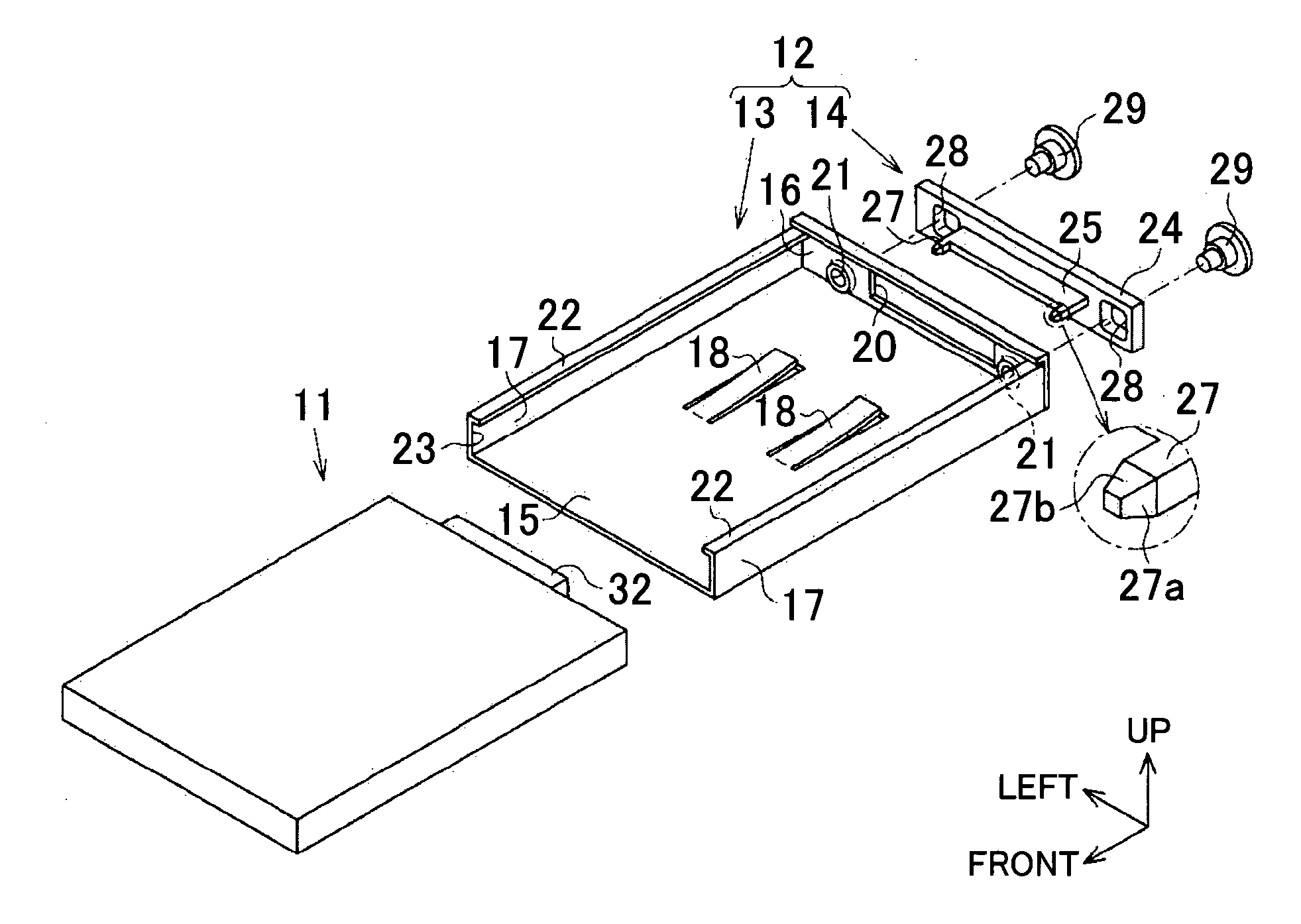
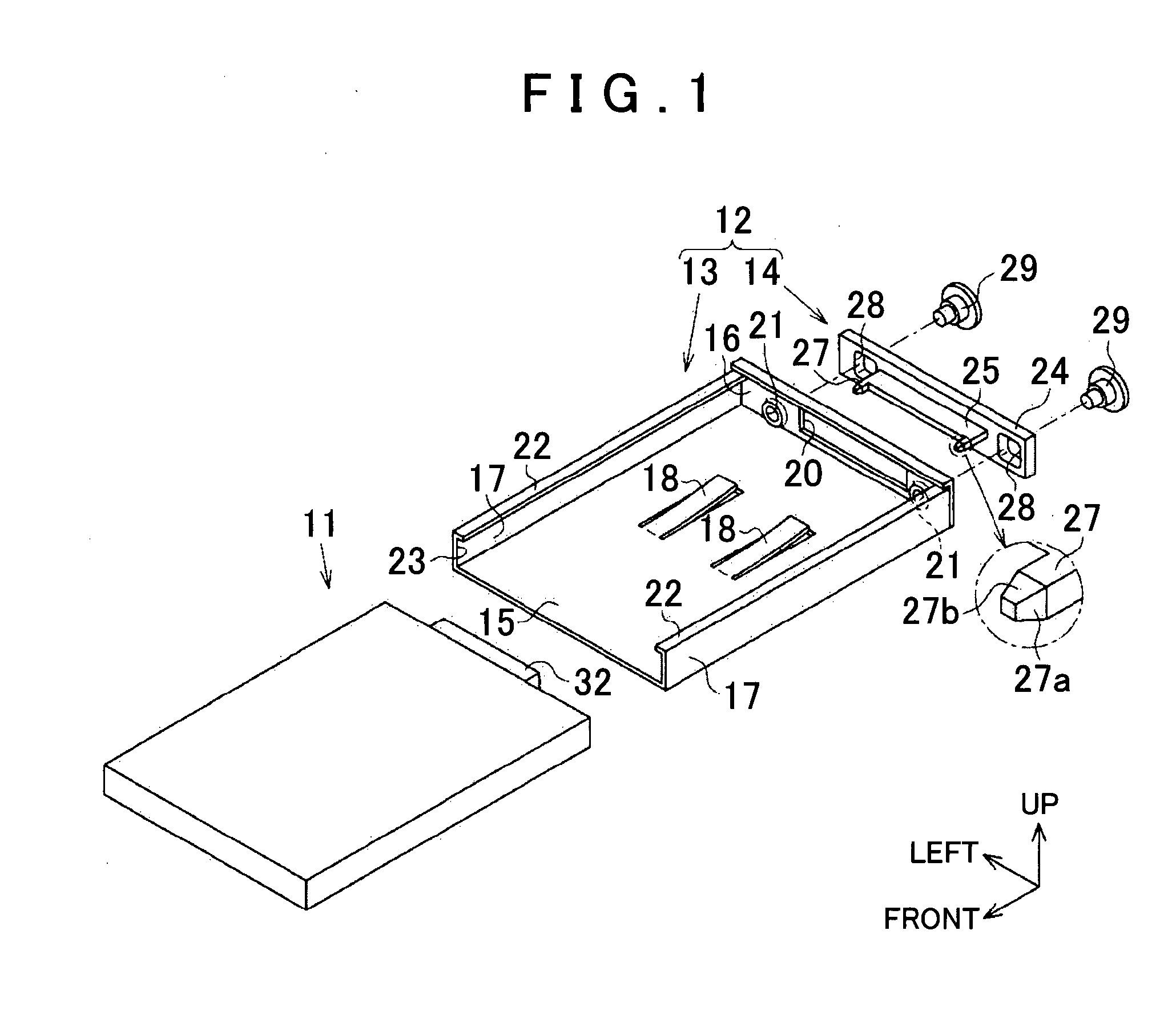
[0033]FIG. 1 is an exploded perspective view that, among components of a navigation device, shows a hard disk device 11 serving as an electronic device mounted to a holder device 12.

[0034]As illustrated in FIG. 1, the holder device 12 includes a holder body 13 having a substantially frame-like configuration, and a connector body 14 that is attached to the holder body 13.

[0035]The holder body 13 includes a bottom plate 15 having a rectangular plate shape, a back plate 16 that is provided standing on an end edge located on the back side of the bottom plate 15, and a pair of side plates 17 that are provided standing on end edges located on both left an...


PUM


Abstract

A connector portion of a hard disk device is provided with a recess portion that guides a connector portion of a holder device so as to align the connector portion of the holder device with the connector portion of the hard disk device. The connector portion of the holder device is provided with a guide projection that is guided by the recess portion. A connector body is attached to a holder body shiftable within a range that the connector portion of the holder device can follow the connector portion of the hard disk device and a range that the guide projection can be guided by the recess portion.

Description

TECHNICAL FIELD[0001]The present invention relates to a connector coupling structure that, when an electronic device is inserted into a holder device, electrically connects a connector terminal of a first connector provided in the electronic device and a connector terminal of a second connector provided in the holder device, and relates to a holder device that is electrically connected to an electronic device through the connector coupling structure.BACKGROUND ART[0002]As vehicle navigation devices, there are known navigation devices having a configuration in which a hard disk device, that is, an electronic device, is detachably mounted to a holder device. In such navigation devices, a connector that is provided on the hard disk device side and a connector that is provided on the holder device side may have manufacturing errors. For this reason, the connectors may not be suitably aligned when mounting the hard disk device to the holder device, making it difficult to connect connecto...

Claims


Application Information

Patent Timeline
IPC IPC(8): H01R13/631
CPCH01R12/7005H01R13/6315
Inventor TAKEI, EIICHIARAKI, HIROYOSHIIZUMI, TAKEMUNESAITO, TATSUO
Owner AISIN AW CO LTD
Why Eureka
Try Eureka