
Method for forming dental coating and dental cad/cam device

a technology of cad/cam and dental coating, which is applied in the direction of impression caps, instruments, teeth capping, etc., can solve the problems of high price of x-ray equipment, inability to accurately measure the internal structure of a target object, and adversely affect the measurement accuracy, etc., to achieve accurate formation, accurate measurement, and high resolution

Inactive Publication Date: 2012-12-20
HEALTH SCI TECH TRANSFER CENT JAPAN HEALTH SCI FOUND
View PDF12 Cites 104 Cited by
  • Summary
  • Abstract
  • Description
  • Claims
  • Application Information

AI Technical Summary

Problems solved by technology

In measuring the model or the dental impression material, however, colors and surface conditions of the model or the dental impression material adversely affect the measurement accuracy in some cases.
Accordingly, it is difficult to accurately measure the internal structure of a target object.
The high price of X-ray equipment also inhibits widespread use thereof.
However, this method directly measures the 3D shape in a mouth, and thus, has low accuracy.
It is particularly difficult to obtain shape data on a portion below the gingival margin to which no light reaches.
This necessity involves a heavy burden on patients.
It is difficult to obtain information below the gingival margin in the case of a dental prosthesis material such as a crown.
Accordingly, it is difficult to form a dental restorative / prosthesis material with a high accuracy of fitness based on 3D shape data obtained from an image only of the surface of intraoral tissues.
In addition, since diffuse reflection and transmission occur on the tooth surface, measurement with intraoral cameras is not accurate.
Conventional morphology measurements cannot accurately morphologically measure the margin between a dental restorative / prosthesis material and a target teeth of treatment.
These measurements insufficiently reduce secondary dental caries, periodontal diseases, fractures, cracks, etc.

Method used


Image

  • Method for forming dental coating and dental cad/cam device
  • Method for forming dental coating and dental cad/cam device
  • Method for forming dental coating and dental cad/cam device

Examples


Embodiment Construction

[0027]An embodiment of the present disclosure will be specifically described with reference to the attached drawings. The embodiment below is intended for easy understanding of the principle of the present disclosure. The scope of the invention is not limited to the embodiment below, and includes other embodiments expected by those skilled in the art.

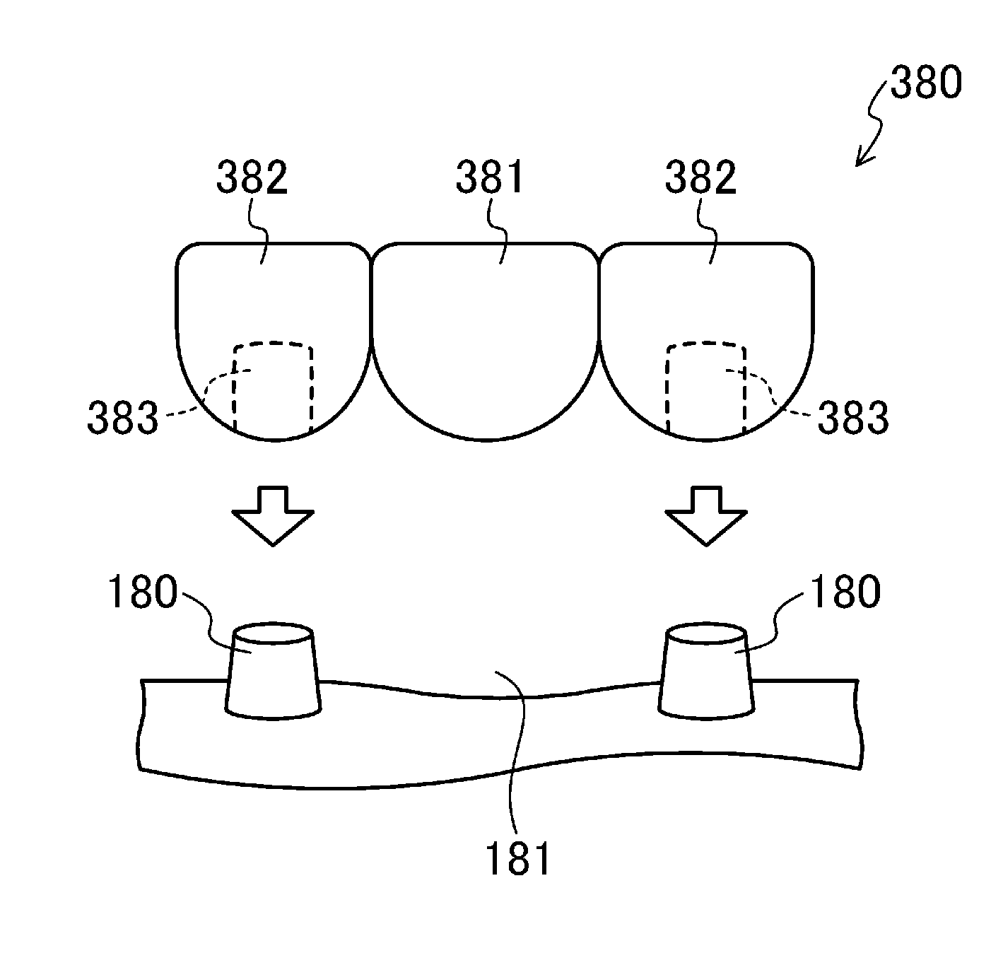
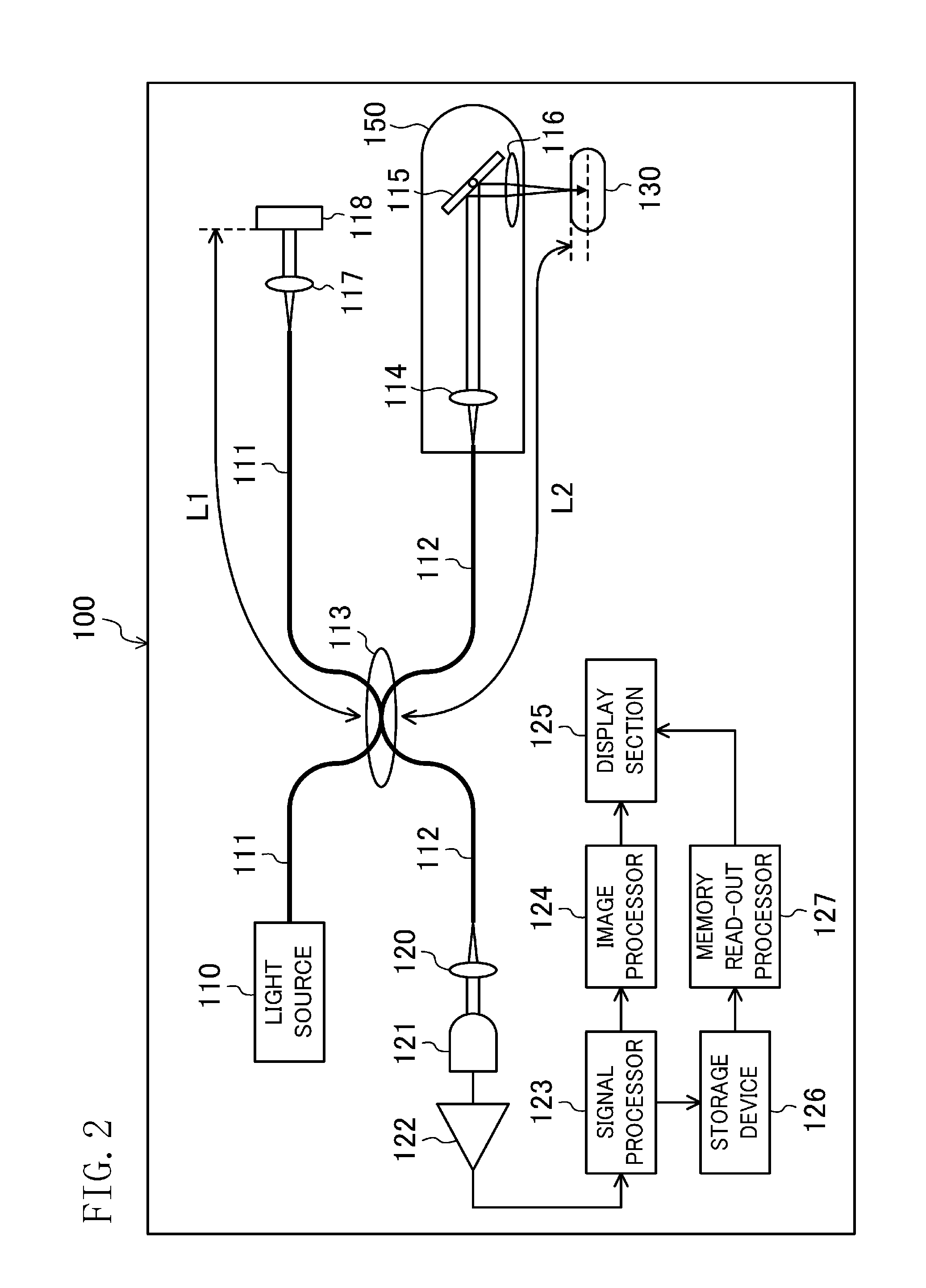
[0028]Inventors of the present disclosure arrived at the invention based on the fact that accurate measurement of an intraoral site can be ensured even below the gingival margin by using optical coherent tomography (OCT). Specifically, an intraoral site or a dental impression (i.e., a model for forming a dental coating) of a tooth and jaw obtained from a dental impression material is measured with an OCT device, thereby obtaining multiple pieces of tomogram information. Based on the obtained multiple pieces of tomogram information, 3D shape data is created. Using the 3D shape data for a dental coating, a dental coating is formed.

[0029]T...


PUM


Abstract

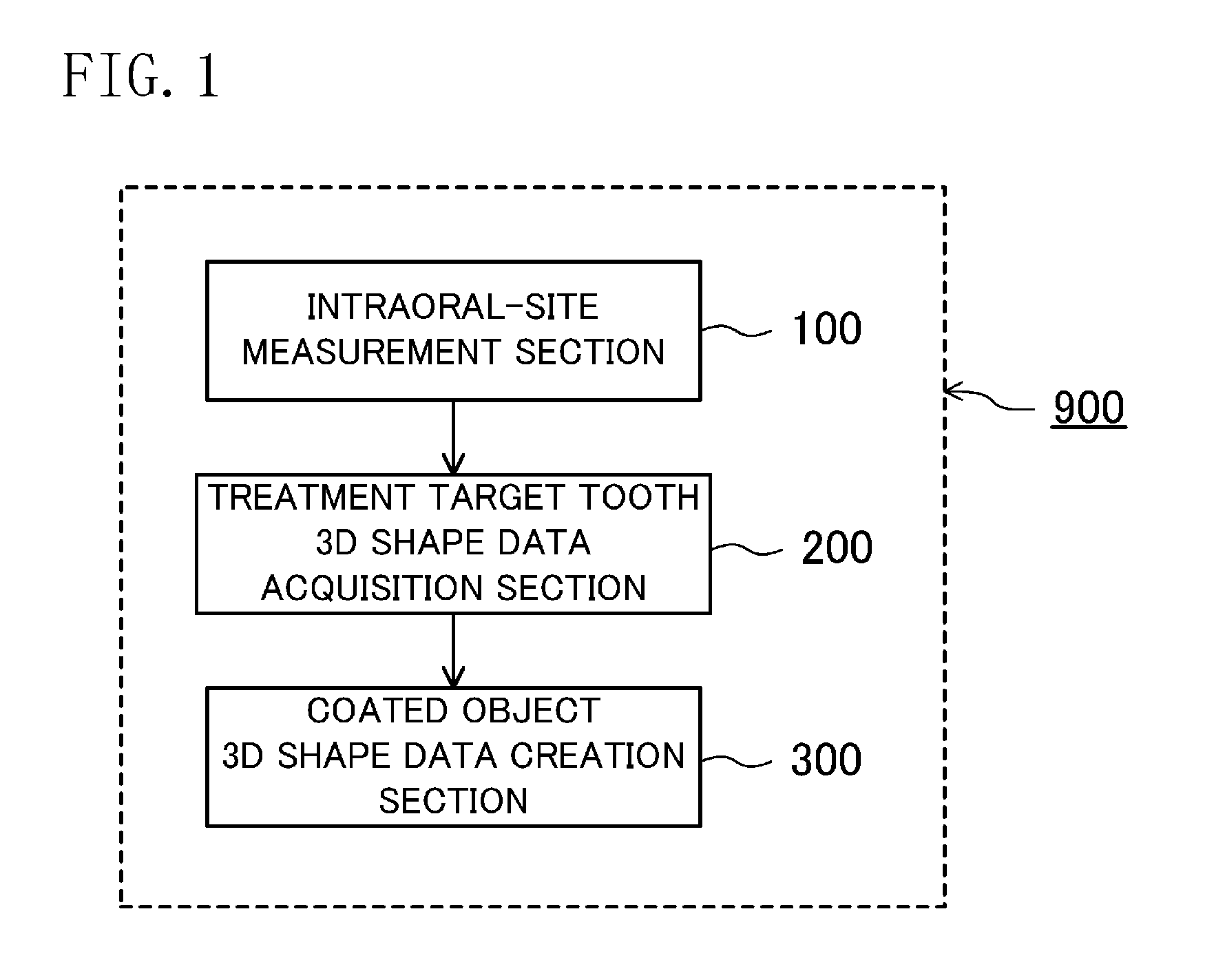
A dental CAD / CAM device capable of accurately forming a dental coating is provided. The device includes: an intraoral-site measurement section 100 configured to measure 3D shape data on an intraoral site 130 with an OCT probe 150 for obtaining a tomogram of an object using near-ultraviolet light; a treatment-target-tooth 3D shape data acquisition section 200 configured to acquire shape data of a treatment target tooth from 3D shape data obtained by the intraoral-site measurement section 100; and a coating object 3D shape data creation section 300 configured to create 3D shape data on a dental coating such that the dental coating matches the 3D shape data of the treatment target tooth obtained by the treatment target tooth 3D shape data acquisition section 200.

Description

TECHNICAL FIELD[0001]The present disclosure relates to methods for accurately forming dental coatings and dental CAD / CAM devices.BACKGROUND ART[0002]In dental clinical treatments, dental treatment is performed by filling cavities in teeth with restorative materials such as inlays or onlays, or prosthesis materials such as crowns, bridges, or implants. To obtain morphological information on a cavity in a tooth or morphological information on the inside of a mouth, for example, an indirect model of teeth or the inside of a mouth is formed using a dental impression material by a lost-wax process or other processes. Using this indirect model as a mold, a restorative material or a prosthesis material is formed.[0003]Dental restorative / prosthesis materials (dental coatings) are conventionally formed with so-called CAD / CAM devices using computer-aided design (CAD), i.e., design with computers, and computer-aided manufacturing (CAM) of cutting out prosthesis materials by computer control. I...

Claims


Application Information

Patent Timeline
Patent Type & Authority Applications(United States)
IPC IPC(8): A61B6/14A61C5/10A61C13/003A61C5/00A61B6/51A61C5/77
CPCA61C9/0053A61C13/0004A61C5/77G01B9/02091G01B11/2441
Inventor OZAWA, NOBUYOSHISUMI, YASUNORI
Owner HEALTH SCI TECH TRANSFER CENT JAPAN HEALTH SCI FOUND
Learn More