Ventilation mask with integrated piloted exhalation valve and method of ventilating a patient using the same

a technology of exhalation valve and ventilation mask, which is applied in the field of ventilation mask, can solve the problems of high non-compliance rate and high non-compliance rate of cpap therapy, and achieve the effects of reducing noise generated by the mask, preventing patient discomfort, and alleviating patient discomfor

Active Publication Date: 2012-12-27
BREATHE TECHNOLOGIES INC
View PDF4 Cites 15 Cited by
  • Summary
  • Abstract
  • Description
  • Claims
  • Application Information

AI Technical Summary

Benefits of technology

[0014]One of the primary benefits attendant to including the valve inside the mask is that it provides a path for patient-expired CO2 to exit the system without the need for a dual-limb patient circuit, and without the disadvantages associated with traditional single-limb patient circuits. For instance, in applications treating patients with sleep apnea, having the valve inside the mask allows patients to fall asleep while wearing the mask without the treatment pressure turned on, thereby preventing patient discomfort typically experienced with falling asleep while breathing at a positive pressure. In accordance with the present invention, the sensing described above may be used to sense a predetermined event, such as a set time, the detection of an event indicating patient airway obstruction, or the detection of a patient falling asleep, and start the positive airway pressure therapy upon sensing any such event, unlike existing devices which attempt to alleviate patient discomfort by starting at a lower pressure level (typically 4 cmH2O) and ramping the pressure up to a therapeutic level over a period of time. Additionally, having a valve inside the mask mitigates the need to have vent holes within the patient mask (a typical feature of mask used for sleep apnea) coincident with a purge flow to bleed patient expired CO2 from the system. Alleviating the mask vent holes and associated extra flow of gas through the mask helps reduce noise generated by the mask, reduce CO2 re-breathing, reduce patient nose dryness cause by excess gas flowing past the patient, and reduce flow requirements of the ventilator. Yet another benefit of the mask without vent holes and having the valve inside the same is that because there is not a constant flow through the mask and out of any vent holes, a heat moisture exchanger can also be incorporated into the mask, allowing a simple method of providing heated and humidified gas to the patient.
[0015]Another benefit for having the valve inside the mask is that it allows for a significant reduction in the tubing size, as it supports the ventilator delivering higher pressures than the patient's therapeutic pressure. In this regard, pressure from the ventilator is significantly higher than the patient's therapeutic pressure. Pressure sensing can be implemented inside the mask near the patient interface port(s), facilitating the ventilator to have a means to servo control pressure at the patient interface port(s). Having higher pressure from the ventilator and an active exhalation valve in the mask allows for the tubing size to be significantly smaller (e.g. 1-9 mm ID) compared to conventional ventilators (22 mm ID for adults / 15 mm ID for pediatric). One obvious benefit of smaller tubing is that it provides less bulk for patient and / or caregivers to manage. For today's smallest ventilators, the bulk of the tubing is as significant as the bulk of the ventilator. Another benefit of the smaller tubing is that is allows for more convenient ways of affixing the mask to the patient. For instance, the tubing can go around the patient's ears to hold the mask to the face, instead of requiring straps (typically called “headgear”) to affix the mask to the face. Along these lines, the discomfort, complication, and non-discrete look of the headgear is another significant factor leading to the high non-compliance rate for CPAP therapy. Another benefit to the smaller tubing is that the mask can become smaller because it does not need to interface with the large tubing. Indeed, large masks are another significant factor leading to the high non-compliance rate for CPAP therapy since, in addition to being non-discrete, they often cause claustrophobia.

Problems solved by technology

Along these lines, the discomfort, complication, and non-discrete look of the headgear is another significant factor leading to the high non-compliance rate for CPAP therapy.
Indeed, large masks are another significant factor leading to the high non-compliance rate for CPAP therapy since, in addition to being non-discrete, they often cause claustrophobia.

Method used


Image

  • Ventilation mask with integrated piloted exhalation valve and method of ventilating a patient using the same
  • Ventilation mask with integrated piloted exhalation valve and method of ventilating a patient using the same
  • Ventilation mask with integrated piloted exhalation valve and method of ventilating a patient using the same

Examples


first embodiment

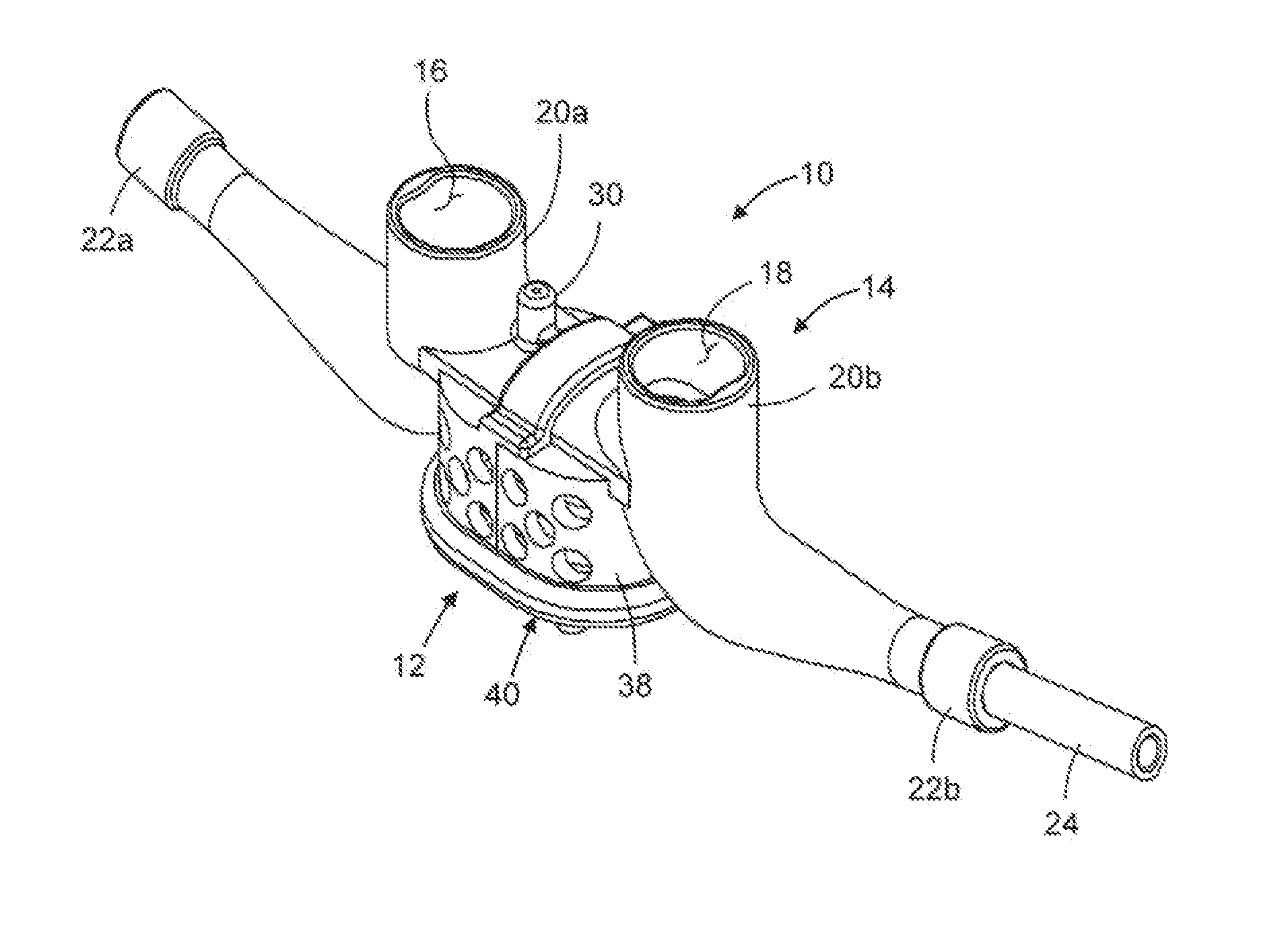
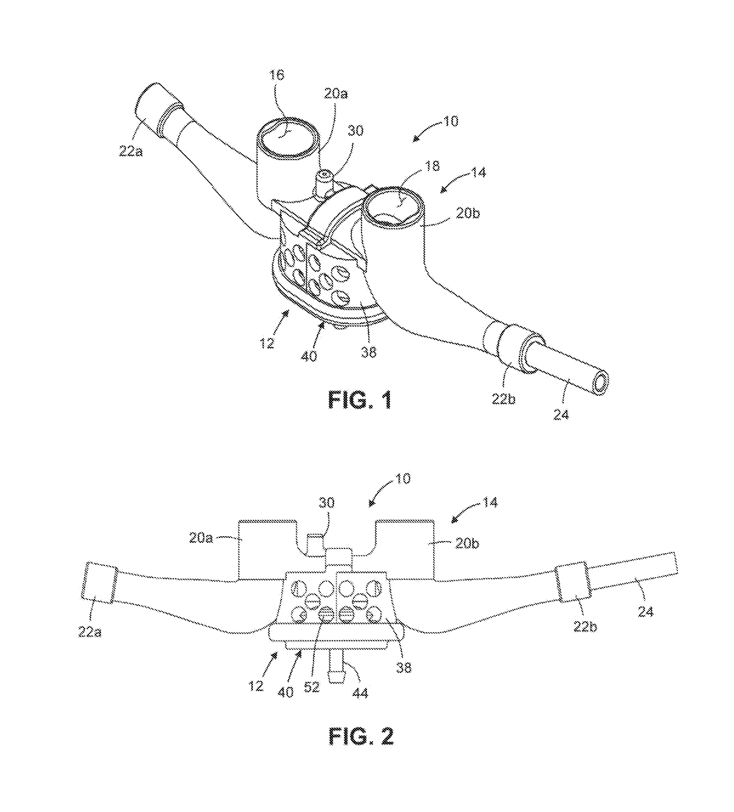
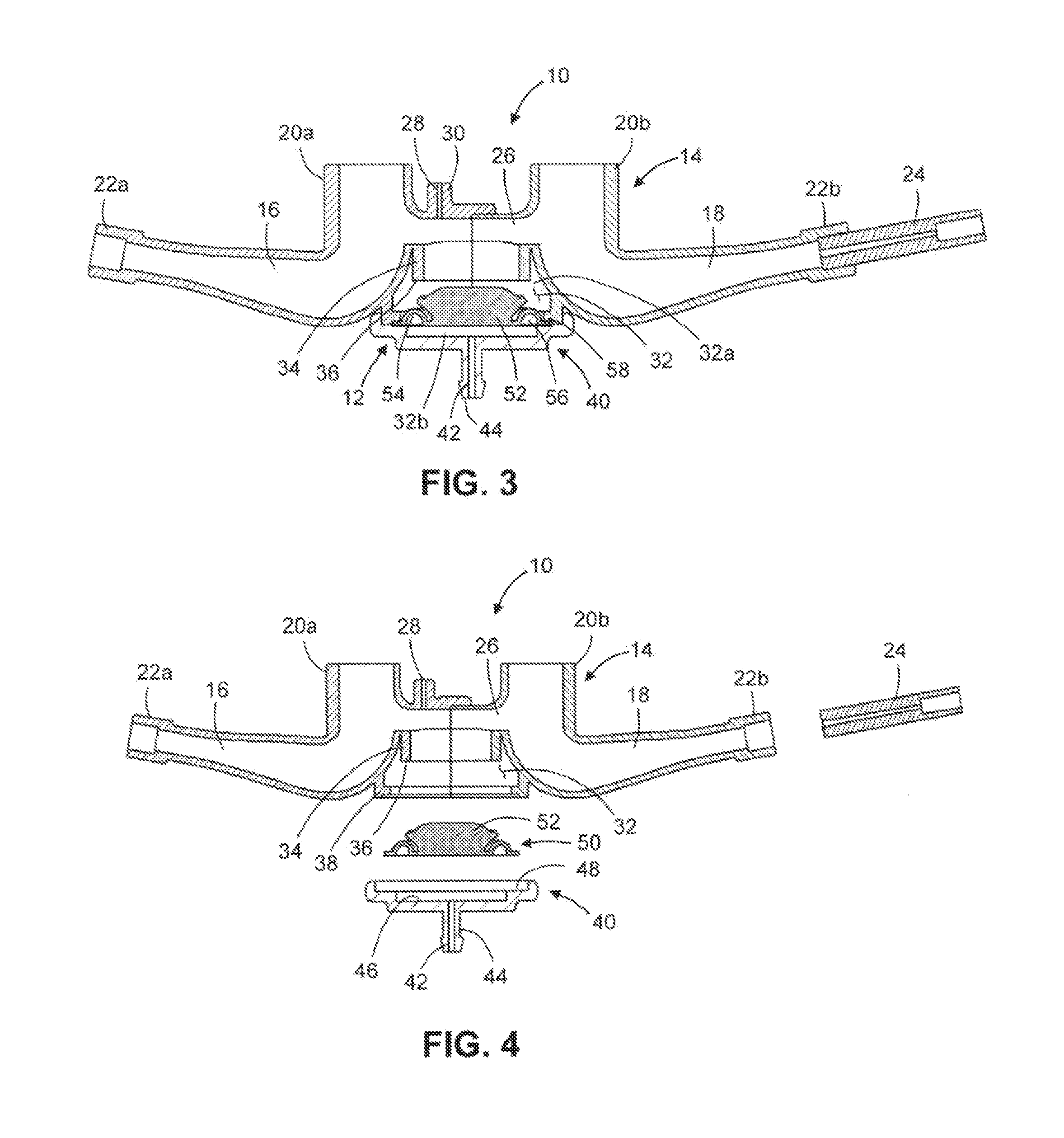
[0028]Referring now to the drawings wherein the showings are for purposes of illustrating various embodiments of the present invention only, and not for purposes of limiting the same, FIGS. 1-4 depict a ventilation mask 10 constructed in accordance with the present invention. The mask is depicted as a nasal prongs mask, however those skilled in the art will recognize that other ventilation masks are contemplated herein such as nasal pillows masks, nasal masks and oronasal masks and for purposes of this application the term mask and / or ventilation mask will include all such mask structures. Additionally, for purposes of this application, the term “direct nasal interface mask” will be deemed to encompass those masks which are configured to facilitate the direct introduction of therapeutic fluid pressure into the nostrils of a patent, such masks including, but not being limited to, nasal pillows masks, nasal prongs masks, and nasal cradle masks. The mask 10 includes an integrated, diap...

second embodiment

[0045]Referring now to FIGS. 5-9, there is shown a nasal pillows mask 100 constructed in accordance with the present invention. The mask 100 includes an integrated, flapper-implemented exhalation valve 112, the structural and functional attributes of which will be described in more detail below.

[0046]As seen in FIGS. 5-9, the mask 100 comprises a housing 114 which defines first and second fluid flow passages 116, 118. As seen in FIGS. 8 and 9, the flow passages 116, 118 are formed within the housing 114 to have substantially identical shapes or contours. As with the first embodiment of this invention, a single flow passage is additionally expressly contemplated herein. In the mask 100, one end of each of the flow passages 116, 118 is defined by a respective one of an identically configured pair of generally cylindrical, tubular protrusions 120a, 120b of the housing 114. The opposite end of each of the flow passages 116, 118 is defined by a respective one of an identically configured...


PUM


Abstract

In accordance with the present invention, there is provided a mask for achieving positive pressure mechanical ventilation (inclusive of CPAP, ventilator support, critical care ventilation, emergency applications), and a method for a operating a ventilation system including such mask. The mask of the present invention includes a piloted exhalation valve that is used to achieve the target pressures/flows to the patient. The pilot for the valve may be pneumatic and driven from the gas supply tubing from the ventilator. The pilot may also be a preset pressure derived in the mask, a separate pneumatic line from the ventilator, or an electro-mechanical control. Additionally, the valve can be implemented with a diaphragm or with a flapper.

Description

CROSS-REFERENCE TO RELATED APPLICATIONS[0001]The present application claims priority to U.S. Provisional Patent Application Ser. No. 61 / 499,950 entitled VENTILATION MASK WITH INTEGRATED PILOTED EXHALATION VALVE filed Jun. 22, 2011, and U.S. Provisional Patent Application Ser. No. 61 / 512,750 entitled VENTILATION MASK WITH INTEGRATED PILOTED EXHALATION VALVE AND METHOD OF VENTILATING A PATIENT USING THE SAME filed Jul. 28, 2011STATEMENT RE: FEDERALLY SPONSORED RESEARCH / DEVELOPMENT[0002]Not ApplicableBACKGROUND OF THE INVENTION[0003]1. Field of the Invention[0004]The present invention relates to systems and methods for controlling delivery of a pressurized flow of breathable gas to a patient and, more particularly, to a ventilation mask such as a nasal mask, nasal prongs mask or nasal pillows mask for use in critical care ventilation, respiratory insufficiency or PAP (Positive Airway Pressure) therapy and incorporating a piloted exhalation valve inside the mask.[0005]2. Description of ...

Claims


Application Information

Patent Timeline
Patent Type & Authority Applications(United States)
IPC IPC(8): A61M16/06A61M16/00A61M16/20
CPCA61M16/0666A61M16/0875A61M16/1045A61M16/0833A61M16/201A61M2205/3334A61M16/0003A61M16/0622A61M16/208A61M2016/0027A61M16/207A61M16/0605A61M16/0858A61B5/4836A61B5/03A61B5/087A61B5/097
Inventor ALLUM, TODD W.CIPOLLONE, JOSEPH
Owner BREATHE TECHNOLOGIES INC
Why Eureka
Try Eureka