Housing for aircraft mounted components

a technology for aircraft and components, applied in the direction of transportation and packaging, using reradiation, instruments, etc., can solve the problems of corroding the chassis and antenna assembly, placing a great deal of stress on the components of the tcas device, and affecting the performance of the antenna assembly,

Active Publication Date: 2012-12-27
PTI INDS
View PDF1 Cites 20 Cited by
  • Summary
  • Abstract
  • Description
  • Claims
  • Application Information

AI Technical Summary

Benefits of technology

[0008]According to another aspect of the invention, a method of producing a device that will be mounted to an exterior of an aircraft is provided. The method includes receiving an assembly having a radome, a chassis mounted to one side of the radome and a skirt member. A first flat housing layer is formed having a first end, a second end, a first side and a second side. The assembly is placed onto the first flat housing layer. The first end, the second end, the first side and the second side are bent about the assembly to form a housing, the housing being arranged in a lap joint arrangement with the radome and the chassis. The housing is cured.

Problems solved by technology

This wide range of operating temperatures places a great deal of stress on the components of the TCAS device.
In particular, the bonding layer between the chassis and the radome is subjected to stresses due to the disparity between the coefficients of thermal expansion of the chassis and the radome.
Repeated thermal cycling of the TCAS device may then result in a breach in the bonding layer allowing condensation to migrate into the interior portion of the TCAS device.
The entry of the condensation may then result in corrosion of the chassis and antenna assembly.

Method used


Image

  • Housing for aircraft mounted components
  • Housing for aircraft mounted components
  • Housing for aircraft mounted components

Examples


Embodiment Construction

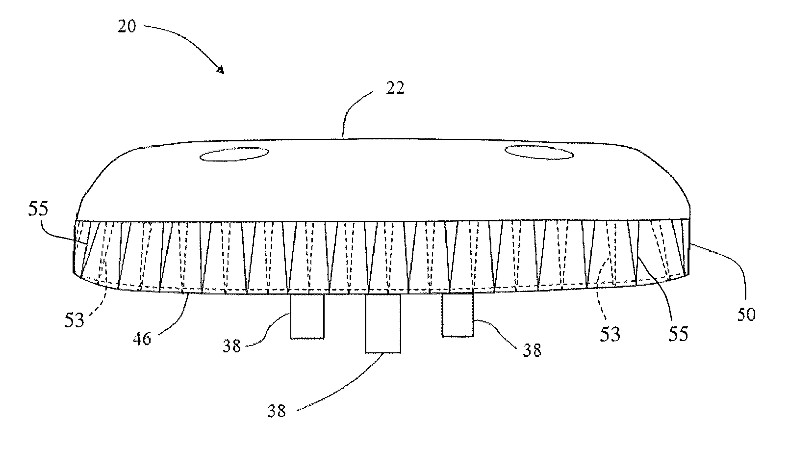
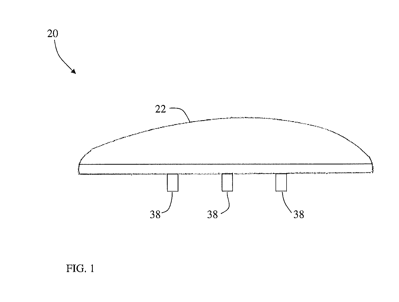
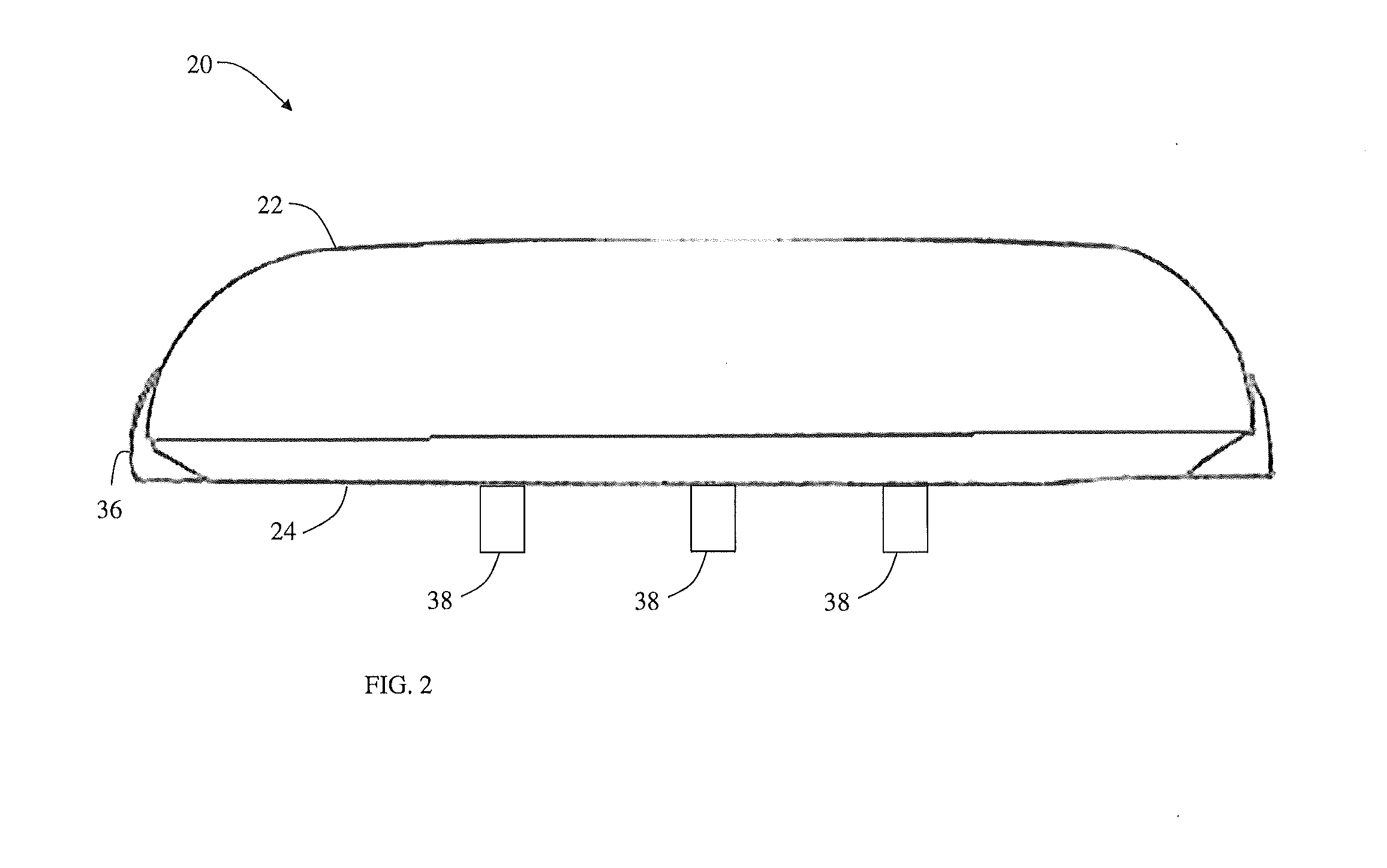
[0026]An exemplary embodiment of a traffic collision avoidance system (TCAS) device 20 is illustrated in FIGS. 1-7. As will be discussed in more detail herein, the TCAS device 20 includes a housing that has a Coefficient of Thermal Expansion (CTE) that is similar to or equal to the CTE of a fiberglass skirt layer. The TCAS device 20 provides number of advantages in preventing corrosion to increase reliability and to extend useful operating life of the TCAS device 20.

[0027]It should be appreciated that while the exemplary embodiment makes reference to a TCAS device 20, the claimed invention should not be so limited. The TCAS device 20 may also be a wide angle augmentation system (WAAS), a European geostationary navigation overlay service (EGNOS), a multi-functional satellite augmentation system (MSAS), or other type of navigation augmentation system for aircraft. Further, in some embodiments, the TCAS device 20 may be any device having a sealed interior portion that is mounted to the...


PUM

PropertyMeasurementUnit
temperatureaaaaaaaaaa
tensile strengthaaaaaaaaaa
cure temperatureaaaaaaaaaa

Abstract

A traffic collision avoidance system (TCAS) device is provided. The device includes a radome having an antenna. A chassis is bonded to said radome about a periphery by a skirt layer. A housing is adhesively bonded to the radome, the skirt layer and the chassis. The housing has a substantially flat bottom portion with a wall extended about a periphery, the wall forming a lap joint with the chassis and radome.

Description

CROSS-REFERENCE TO RELATED APPLICATIONS[0001]The present application is a Continuation-in-Part application of U.S. patent application Ser. No. 12 / 720,051 filed on Mar. 9, 2010 which is incorporated herein by reference in its entirety.BACKGROUND OF THE INVENTION[0002]The subject matter disclosed herein relates in general to a housing for mounting components to an exterior of an aircraft, and in particular to a composite housing for traffic collision avoidance system (TCAS) type devices that minimizes or prevents the occurrence of corrosion due to environmental contaminants.[0003]In areas of congested airspace or low visibility, it is desirable for a pilot of one aircraft to be warned of the presence of a nearby aircraft so the respective aircraft may maneuver the aircraft to avoid collision. One device, known as a traffic collision avoidance system (TCAS) employs a transponder mounted on the aircraft that communicates with transponders on nearby aircraft. In this way, the aircraft co...

Claims


Application Information

Patent Timeline
Patent Type & Authority Applications(United States)
IPC IPC(8): G01S13/93B32B3/04G01S13/933
CPCG01S13/9303H01Q1/28Y10T156/1034B64C1/36H01Q1/42G01S13/933G08G5/04
Inventor HILL, JOHN LESLIE PAUL
Owner PTI INDS
Why Eureka
Try Eureka