Visual displays for an aircraft flight deck

Inactive Publication Date: 2012-12-27
GE AVIATION SYST LTD
View PDF3 Cites 15 Cited by
  • Summary
  • Abstract
  • Description
  • Claims
  • Application Information

AI Technical Summary

Problems solved by technology

Under night conditions that same amount of brightness may render the display too bright for use and could interfere with a pilot's ability to readily view and perceive other less luminous objects.

Method used


Image

  • Visual displays for an aircraft flight deck
  • Visual displays for an aircraft flight deck
  • Visual displays for an aircraft flight deck

Examples


Embodiment Construction

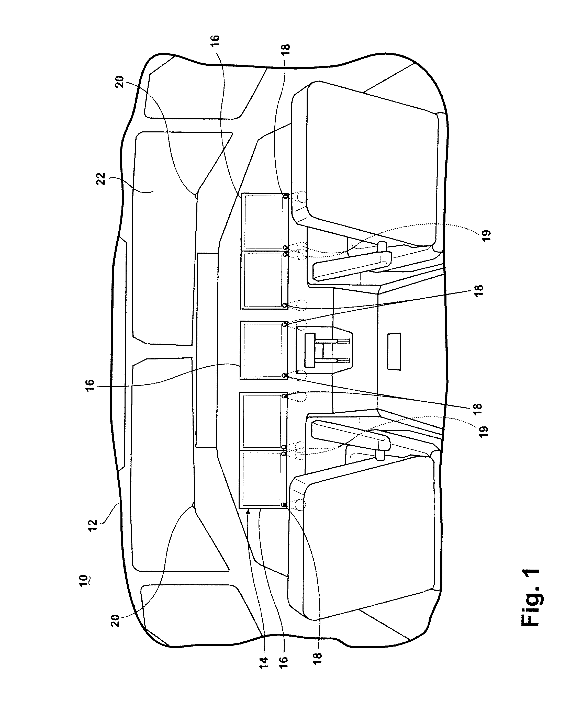
[0011]FIG. 1 illustrates a portion of a prior art aircraft 10 having a cockpit 12 with a flight deck 14 having multiple head down displays 16. The head down displays 16 are typically illuminated and capable of having various brightness levels depending on ambient lighting in the cockpit 12. Ambient light sensors 18 are typically located on the displays 16 and typically detect light that falls directly on the ambient light sensor 18. The ambient light sensors 18 measure luminance that falls directly on the sensor 18, which defines an effective field of view 19 for the sensor 18, which is relatively limited compared to the cockpit 12. The field of view 19 is illustrated as a cone, which identifies the area in which light may fall on the sensor. Depending on the shape and angle of the sensor 18, the cone may be bigger or smaller than illustrated and may be angled differently than as illustrated. Depending on its position relatively to the source of the ambient light, such as the sun, t...


PUM


Abstract

A cockpit for an aircraft includes a windscreen through which light may pass, at least one seat spaced from and facing the windscreen, a flight deck having at least a portion disposed below the windscreen and having at least one head down display having an adjustable brightness that may be set by a brightness signal, a camera having a field of view including at least a portion of the at least one seat and outputting an image signal indicative of luminance information within the field of view, and a processor operably coupled to the camera and the head down display and configured to receive the image signal, determine a luminance of at least a portion of the field of view, determine a brightness for the head down display based on the determined luminance, and outputting to the head down display a brightness signal corresponding to the determined brightness.

Description

CROSS-REFERENCE TO RELATED APPLICATIONS[0001]This application claims priority under 35 U.S.C. §119 to British Patent Application No. 11105731, filed Jun. 22, 2011, the disclosure of which is incorporated herein by reference.BACKGROUND OF THE INVENTION[0002]Contemporary aircraft cockpits include a flight deck having one or more head down displays (HDD), which display to the pilot and flight crew a wide range of aircraft, flight, navigation, and other information used in the operation and control of the aircraft. The displays may be illuminated to help pilots view and locate the relevant information. The brightness is varied in response to the ambient lighting conditions to provide the pilots better visibility of the displayed information. For example, during normal daylight conditions it may be necessary to illuminate the display to a high brightness level so that the pilot may easily view the display. Under night conditions that same amount of brightness may render the display too b...

Claims


Application Information

Patent Timeline
IPC IPC(8): G06F3/038
CPCG09G2320/0626G09G5/10G02B27/01G09G2380/12G06F3/017G02B2027/0138G02B2027/0118G09G2360/144
Inventor DAVIES, JOHN ALUN
Owner GE AVIATION SYST LTD
Why Eureka
Try Eureka