
Data transmission method, base station, and communication system

Active Publication Date: 2012-12-27
HUAWEI TECH CO LTD
View PDF9 Cites 16 Cited by
  • Summary
  • Abstract
  • Description
  • Claims
  • Application Information

AI Technical Summary

Benefits of technology

[0006]By providing a data transmission method, a base station, and a communication system, when uplink data transmission is performed by adopting a semi-persistent scheduling manner, a problem that different user equipments cannot perform data transmission on a same time and frequency resource, which reduces spectrum utilization efficiency, can be solved.
[0018]Through the foregoing data transmission method, base station, and communication system, when the uplink data transmission is performed by adopting the semi-persistent scheduling manner, different user equipments can perform the data transmission on the same time and frequency resource, which improves the spectrum utilization efficiency.

Problems solved by technology

In the prior art, when uplink data transmission is performed by adopting the semi-persistent scheduling manner, different user equipments cannot perform data transmission on a same time and frequency resource, which reduces spectrum utilization efficiency.

Method used


Image

  • Data transmission method, base station, and communication system
  • Data transmission method, base station, and communication system
  • Data transmission method, base station, and communication system

Examples


Embodiment Construction

[0023]An LTE (Long term evolution, long term evolution) system is taken as an example below to explain the embodiments of the present invention in detail.

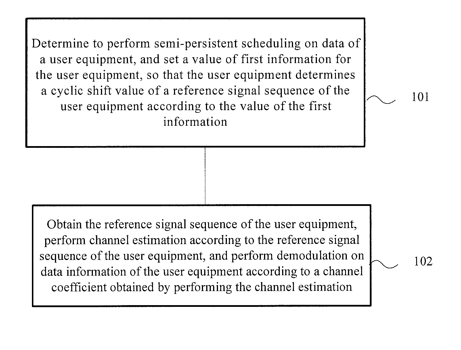
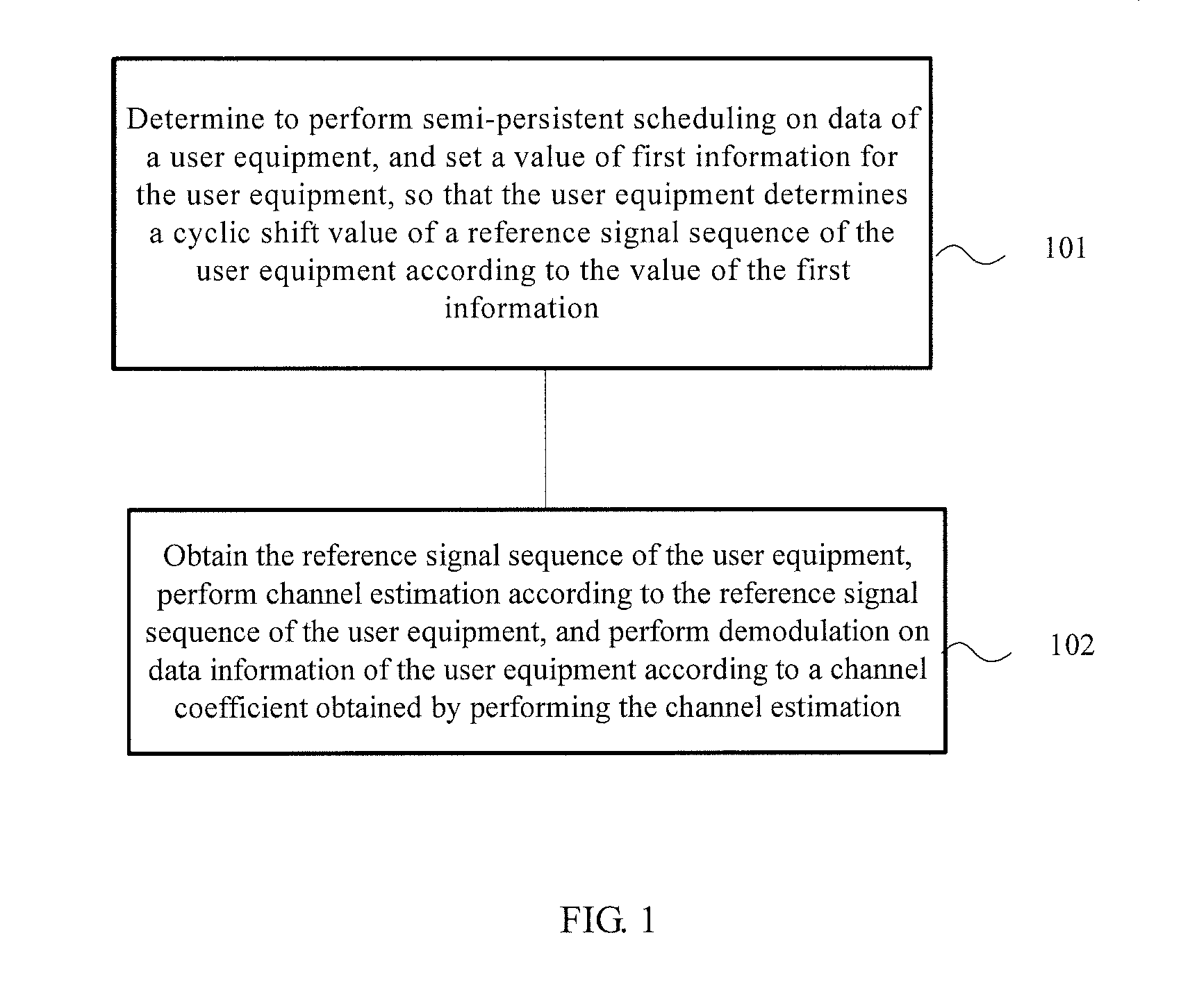
[0024]With reference to FIG. 1, a data transmission method according to an embodiment of the present invention is described in detail below. As shown in FIG. 1, the method may be as follows.

[0025]Step 101: Determine to perform semi-persistent scheduling on data of a user equipment, and set a value of first information for the user equipment, so that the user equipment determines a cyclic shift value of a reference signal sequence of the user equipment according to the value of the first information.

[0026]Step 102: Obtain the reference signal sequence of the user equipment, perform channel estimation according to the reference signal sequence of the user equipment, and perform demodulation on data information of the user equipment according to a channel coefficient obtained by performing the channel estimation.

[0027]According to the...


PUM


Abstract

The present invention discloses a data transmission method, a base station, and a communication system, which are applied in the communication field. The method includes: determining to perform semi-persistent scheduling on data of a user equipment; setting a value of first information for the user equipment, so that the user equipment determines a cyclic shift value of a reference signal sequence of the user equipment according to the value of the first information; and obtaining the reference signal sequence of the user equipment, performing channel estimation according to the reference signal sequence of the user equipment, and performing demodulation on data information of the user equipment according to a channel coefficient obtained by performing the channel estimation.

Description

CROSS-REFERENCE TO RELATED APPLICATIONS[0001]This application is a continuation of International Application No. PCT / CN2011 / 071288, filed on Feb. 25, 2011, which claims priority to Chinese Patent Application No. 201010117174.8, filed on Feb. 25, 2010, both of which are hereby incorporated by reference in their entireties.FIELD OF THE INVENTION[0002]The present invention relates to communications technologies, and in particular, to a data transmission technology.BACKGROUND OF THE INVENTION[0003]A base station in a communication system may perform channel estimation for a physical uplink data channel by using a DMRS (demodulation reference signal, demodulation reference signal) sequence sent by a UE (User Equipment, user equipment). The base station performs demodulation on data information carried on the physical uplink data channel by using a channel coefficient that is estimated by using the DMRS. The demodulation reference signal transmitted by the user equipment is a sequence kno...

Claims


Application Information

Patent Timeline
IPC IPC(8): H04B15/00H04W72/04
CPCH04W72/042H04L5/0051H04W72/1268H04W72/04H04L27/2613H04W72/23
Inventor YU, ZHENGXUE, LIXIAFAN, XIAO'ANLI, CHAOJUN
Owner HUAWEI TECH CO LTD
Learn More