Foot, leg, and arm support for exercise

Inactive Publication Date: 2012-12-27
LORENTZ II ROBERT A
9 Cites 6 Cited by

AI-Extracted Technical Summary

Problems solved by technology

This reduces the chances that the ...

Method used

[0026]Support pads 19 are attached to the tops of the vertical support posts using a cap bracket 20 that is secured to the inner portion of each vertical support post with pins 21. Note that the support pads 19 are shown curved to better fit the limbs of the user. The support pads can also have a thin layer of padding, if desired for additional comfort.
[0030]FIG. 5 is a detail view, of the lower frame 11 with a footplate 37 in place. Here, the vertical posts 14 and 15 have been removed from the lower frame 11. The footplate 37 is positioned between the front portions of the horizontal frame members 12 and secured to them. The footpad 37 is used to hold the frame down when the user is using the resistance bands. When the resistance bands are used, the user stands on the footplate to prevent the frame from lifting. FIG. 6 is a front view of the lower track with the band clips installed in the main track 13 and footplate 37 in place and with resistance bands 36 installed. Here, the eyebolt clips 30 are installed in the track with the vertical support posts in place. In this way, the resistance bands 36 can be used without having to hold the bands with the user's feet (where they can easily slip off)—as is the normal practice for using these bands. It is also unnecessary to remove the vertical support posts when using the resistance bands. Of course, if the user desires, the clips 30...

Benefits of technology

[0013]The instant invention overcomes these difficulties. It is a foot/leg/arm rest that is fully height and width adjustable. In addition, the support cups can be positioned over a wide range of fixed ang...

Abstract

A foot/leg/arm rest that is fully height and width adjustable. In addition, support cups can be positioned over a wide range of fixed angles to accommodate any user. The supports have a wide base that provides strong, firm and stable support for the device when it is used. The invention has two horizontal end members and a central connecting track. Two vertical post supports are positioned in the track and are slidably installed so that they can be positioned at any desired location within the track. In fact, one of the posts can be removed if desired so that only one post is in use. Each post is height adjustable independent of the other. This allows that supports to be positioned at two different levels, if desired. Each post has a support secured to it using a bracket that can be set to a wide range of angles.

Application Domain

Technology Topic

Image

  • Foot, leg, and arm support for exercise
  • Foot, leg, and arm support for exercise
  • Foot, leg, and arm support for exercise

Examples

  • Experimental program(1)

Example

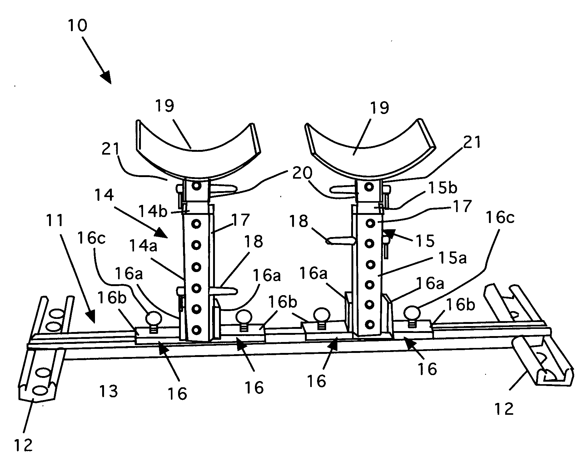
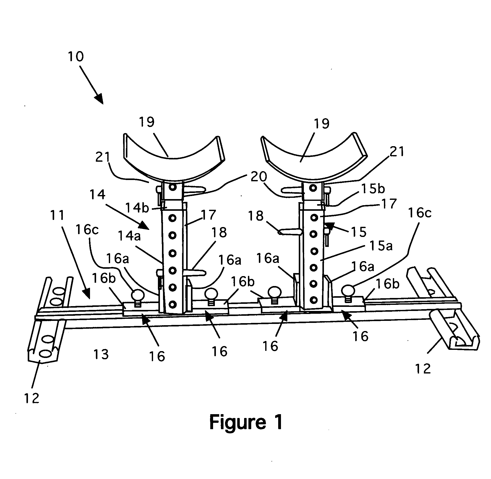
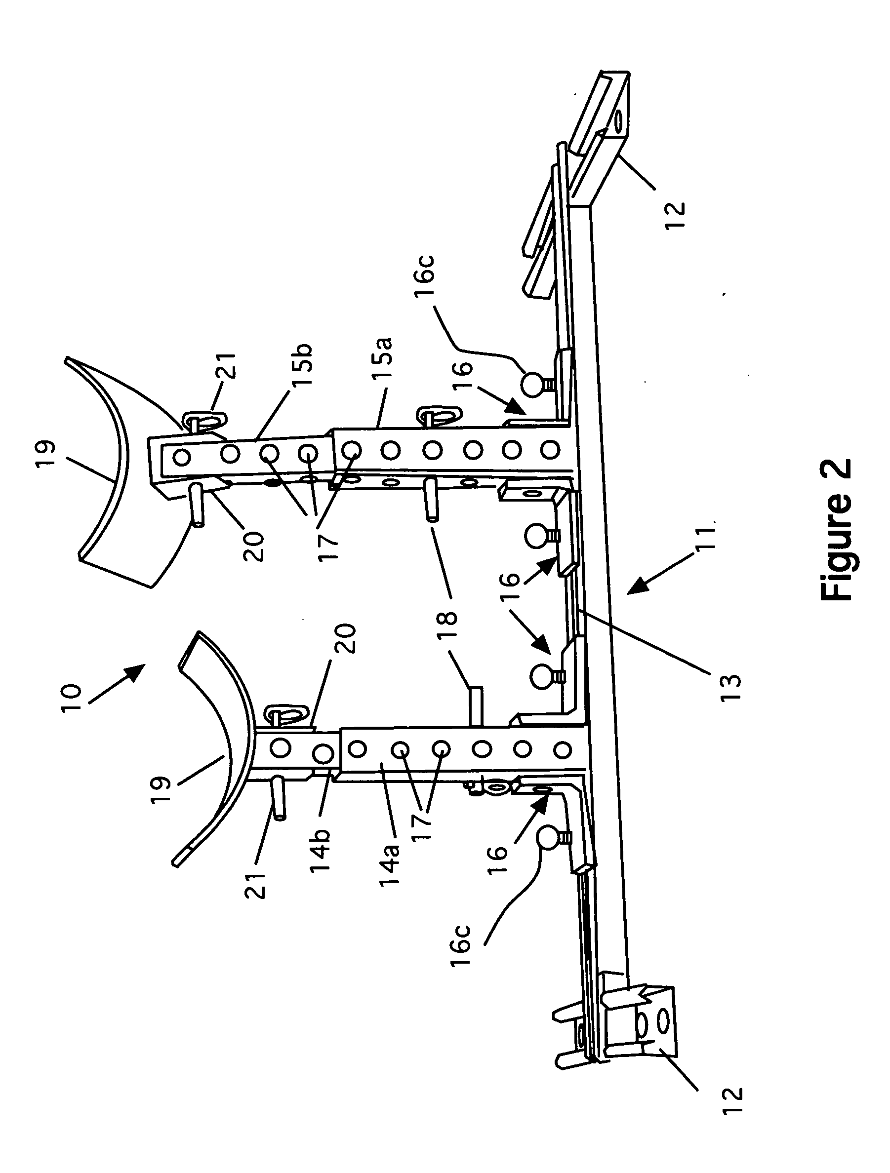
[0024]Referring now to FIG. 1, a front view of the invention 10 is shown. The invention consists of a base 11 that has two horizontal end members 12 and a central connecting track 13. Two vertical post supports 14 and 15 are positioned in the track and are slidably installed in the track so that they can be positioned at any desired location within the track. In fact, one of the posts can be removed if desired so that only one post is in use. The vertical post supports 14 and 15 are secured in the track using locking brackets 16. These brackets have a vertical portion 16a that are secured to the sides of the outer portion of the post supports and a horizontal portion 16b. The horizontal portions 16b have thumb screws 16c that are used to secure the brackets to the track in the desired location. Once tightened, vertical post supports 14 and 15 are firmly help in place.
[0025]Each of the vertical post supports 14 and 15 have and outer portion 14a and 15a and an inner portion 14b and 15b. (See also FIGS. 2 and 3). A series of holes 17 are formed in both the inner and outer portions of the vertical post supports. These holes allow the posts to be height-adjustable. When the inner portion is at the desired height, it is secured with a pin 18 that passes though both the inner and outer portions as shown.
[0026]Support pads 19 are attached to the tops of the vertical support posts using a cap bracket 20 that is secured to the inner portion of each vertical support post with pins 21. Note that the support pads 19 are shown curved to better fit the limbs of the user. The support pads can also have a thin layer of padding, if desired for additional comfort.
[0027]FIG. 2 is a front perspective view of the invention showing one vertical support at a different height from the other, and the leg pad tilted.
[0028]FIG. 3 is a side perspective view of the invention showing one vertical support 15 at a different height from the other 14, and both support pads 19 tilted at different angles with respect to the vertical supports. Note that each post, 14 or 15, is independently height-adjustable, which allows the supports to be positioned at two different levels, if desired. FIG. 2 also clearly shows the inner portion 15b of post 15 in a raised position. As noted above, at the top of each vertical support post is a cap bracket 20 that is secured to the inner portion of each vertical support post with pins 21. Pins are used the preferred embodiment because they require no tools to use, but any other suitable fasteners can be used. Note that the cap brackets are open in the back and front (see, e.g., FIG. 3). This allows the cap brackets to tilt forward or back to any desired angle over almost a full 180 degrees. Obviously, during use, the preferred angles are limited to a range of between about 45 degrees forward or back. This adjustment is made by loosening the fasteners, tiling the support pad to the desired angle and then retightening the fasteners to secure the pad for use.
[0029]FIG. 4 is a side view of an eyebolt clip 30 as an optional embodiment for use with resistance bands. As discussed below, the device can be used to do exercises using resistance bands. To use the bands, eyebolts 30 are installed in lieu of the posts. The eyebolt assembly 30 has a base portion 31 that slides into the track 13. Once positioned, the clip portions 32, which have threads 33, are screwed down until they lock the base portions 31 in place. At the top of the clip portion 32 is a latch clip 34 that has an opening 35 into which the resistance bands 36 (see FIG. 6) fit.
[0030]FIG. 5 is a detail view, of the lower frame 11 with a footplate 37 in place. Here, the vertical posts 14 and 15 have been removed from the lower frame 11. The footplate 37 is positioned between the front portions of the horizontal frame members 12 and secured to them. The footpad 37 is used to hold the frame down when the user is using the resistance bands. When the resistance bands are used, the user stands on the footplate to prevent the frame from lifting. FIG. 6 is a front view of the lower track with the band clips installed in the main track 13 and footplate 37 in place and with resistance bands 36 installed. Here, the eyebolt clips 30 are installed in the track with the vertical support posts in place. In this way, the resistance bands 36 can be used without having to hold the bands with the user's feet (where they can easily slip off)—as is the normal practice for using these bands. It is also unnecessary to remove the vertical support posts when using the resistance bands. Of course, if the user desires, the clips 30 can be installed in the track with the vertical support posts removed-using just the lower frame as shown in FIG. 5, although that is not preferred. Alternatively, the clips 30 can be placed in the two horizontal end members as shown in FIG. 6a. Either of these configurations extends the versatility of the device.
[0031]Resistance band exercises are ideal for home exercise programs and can be used for cardiovascular conditioning as well as for strengthening specific muscle groups. Some of the exercises that can be used with the eyebolt clips and resistance bands include resistance band squats, bent over rowing, diagonal wood chops, triceps extension, lateral rows and bicep curls.
[0032]One of the key exercises that can be done with this device is an exercise called “the plank”. The plank is an isometric exercise that helps build endurance in a user's entire core—rectus abdominus, oblique's, lower back and stabilizing muscles. The exercise itself can cause damage to the elbow if the elbow is not properly protected from the floor. While performing the plank exercise one normally has the elbows directly in contact with the floor, the floor might have carpet or a slight covering on it. This condition can cause discomfort in the elbows while in direct contact with the floor performing the exercise and could cause joint pain or damage the elbows. Using the instant invention and placing the forearms in the padded cups takes away the discomfort of the contact with the floor. The exercise can be performed in a horizontal plane or used with an incline when using the device. This takes the direct floor contact away from the elbows and allows the exercise to be performed focusing on the end results instead of the pain on the elbows due to the floor contact.
[0033]Another option allows the user to grip handgrips directly when performing push-up type exercises. In this embodiment, handgrips are installed in place of the curved pads. FIG. 7 is a side perspective view of the invention as an alternative embodiment showing handgrips 40 in place. In this figure, the frame and vertical supports 14 and 15 are set up as before. However, the curved pads 19 have been removed and handgrips 40 have been added. The handgrips 40 have an open-topped generally rectangular frame 41 and cylindrical grip portions 42. The handgrips are secured to the vertical supports using brackets 43 and pins 21. In this way, the handgrips can be angled front to back, as desired. FIG. 8 shows the handgrips 40 installed on the vertical supports, rotated 90 degrees from the orientation shown in FIG. 7. This option allows the user to grip the handgrips in this manner as well. Note that in this position, the handgrips 40 can be angled from side to side, as desired.
[0034]Note also that both the curved pads and the handgrips can be considered as “exercise supports” for the purposes of this invention.
[0035]Using this platform a user can perform any number of exercises, including push-ups with the legs being supported, the “plank” in which one has the elbows supported by the device instead of having them on the floor, push-ups using the hand grips, and numerous exercises using resistance bands. Thus, this invention provides a safe, comfortable and versatile platform for a user's exercise needs.
[0036]The present disclosure should not be construed in any limited sense other than that limited by the scope of the claims having regard to the teachings herein and the prior art being apparent with the preferred form of the invention disclosed herein and which reveals details of structure of a preferred form necessary for a better understanding of the invention and may be subject to change by skilled persons within the scope of the invention without departing from the concept thereof.

PUM

no PUM

Description & Claims & Application Information

We can also present the details of the Description, Claims and Application information to help users get a comprehensive understanding of the technical details of the patent, such as background art, summary of invention, brief description of drawings, description of embodiments, and other original content. On the other hand, users can also determine the specific scope of protection of the technology through the list of claims; as well as understand the changes in the life cycle of the technology with the presentation of the patent timeline. Login to view more.

Similar technology patents

Classification and recommendation of technical efficacy words

  • Reduce chance
  • Stably support

Lumbar support seat

InactiveUS20130043707A1Stably supportPrevent stressStuffed mattressesChiropractic devicesVertebraEngineering
Owner:YOON WOOK
Why Eureka
Try Eureka