Prosthetic implant and method of implantation

a prosthetic implant and implant technology, applied in the field of knee arthroplasty surgery, can solve the problems of unwanted transformation from a very precisely prepared surface to an imprecise prepared bone surface, inconvenient operation, and inconvenient operation,

Active Publication Date: 2012-12-27
STRYKER CORP
View PDF7 Cites 184 Cited by
  • Summary
  • Abstract
  • Description
  • Claims
  • Application Information

AI Technical Summary

Problems solved by technology

One drawback in utilizing cements or the like is that the required cement layer often results in an unwanted transformation from a very precisely prepared surface to an imprecise prepared bone surface.
This is largely due to the imprecise nature of working with cement.
In a situation where a bone surface has been prepared to meet very specific dimensions, application of cement prior to implanting the implant will result in the surface exhibiting less than precise dimensions.

Method used


Image

  • Prosthetic implant and method of implantation
  • Prosthetic implant and method of implantation
  • Prosthetic implant and method of implantation

Examples


Embodiment Construction

[0087]As used herein, the term “distal” means more distant from the heart and the term “proximal” means closest to the heart. The term “inferior” means toward the feet and the term “superior” means towards the head. The term “anterior” means towards the front part of the body or the face and the term “posterior” means towards the back of the body. The term “medial” means toward the midline of the body and the term “lateral” means away from the midline of the body.

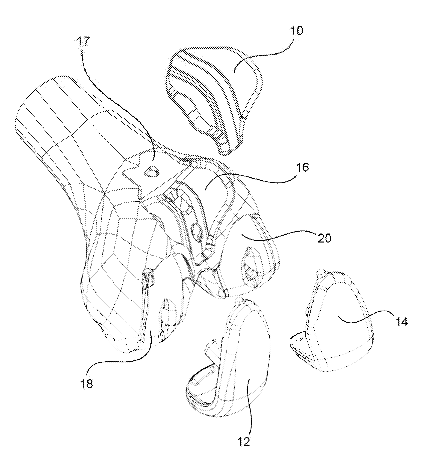
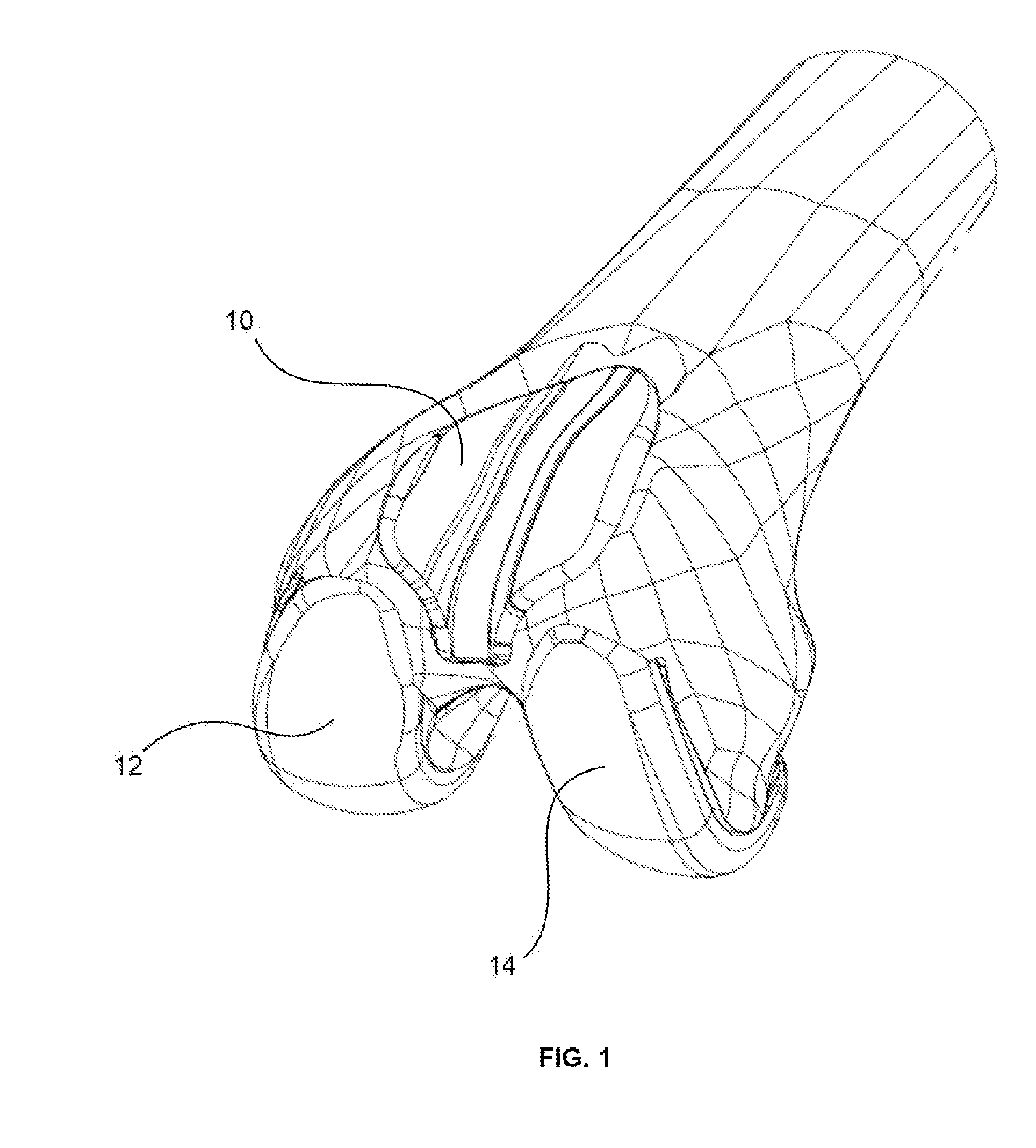
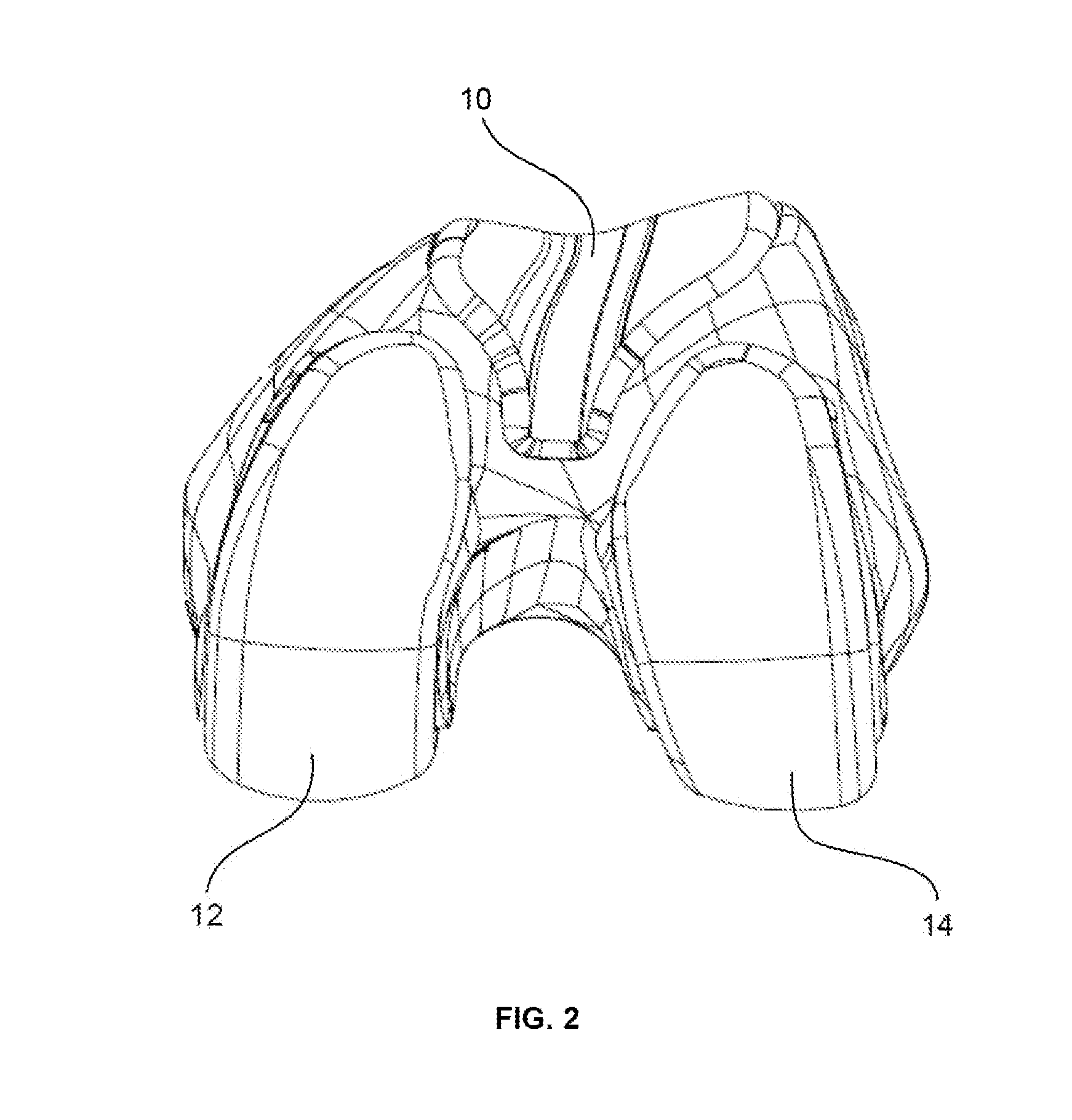
[0088]The present invention addresses the aforementioned shortcomings with certain of the prior art implants. Specifically, the present invention provides implants that can be implanted with or without the use of cement or other adhesive, but remain attached to the bone even in instances where no cement or other adhesive is utilized. Although discussed below primarily in connection with knee arthroplasty procedures, it should be noted that implants according to the present invention can be modified for use in other joints t...


PUM


Abstract

A prosthetic implant useful in a cementless application is disclosed. The implant may include a curved bone facing surface and one or more pegs or keels. Preferably, the implant is implanted on a bone surface that has been prepared so as to allow for a snap fit between the implant and the bone.

Description

CROSS-REFERENCE TO RELATED APPLICATIONS[0001]The present application claims the benefit of the filing date of U.S. Provisional Patent Application No. 61 / 500,257 filed Jun. 23, 2011, the disclosure of which is hereby incorporated herein by reference.BACKGROUND OF THE INVENTION[0002]In a traditional knee arthroplasty surgery, the diseased bone and / or cartilage of a patient is removed and replaced with a prosthetic implant. A surgeon typically prepares the bone using a hand-held oscillating saw blade or other cutting instrument guided by a resection guide or the like, which results in a series of planar bone surface resections. Additionally, the surgeon may use a drill, broach, tamp or other instrument to make holes, slots, depressions or the like in the bone. The planar bone resections and cylindrical bone holes are oriented to interface with flat surfaces and pegs and / or keels formed on a bone engaging surface of a prosthetic implant. An opposite side of the implant includes an artic...

Claims


Application Information

Patent Timeline
Patent Type & Authority Applications(United States)
IPC IPC(8): A61F2/38A61F2/30B25J19/00
CPCA61F2/30771A61F2/3859A61F2/4081A61F2002/3895A61F2002/30889A61F2/3877A61F2002/30891A61B34/00A61B17/1675A61F2/389A61F2/461
Inventor AXELSON, JR., STUART L.FERKO, MICHAEL C.WELLINGS, PETER JOHN
Owner STRYKER CORP
Why Eureka
Try Eureka