Point-based guided importance sampling

a point-based, importance-based technology, applied in the field of computer graphics, can solve problems such as spotty shading, noisy illumination, and unrealistic and unwanted illumination rendering

Active Publication Date: 2013-01-03
DREAMWORKS ANIMATION LLC
View PDF5 Cites 48 Cited by
  • Summary
  • Abstract
  • Description
  • Claims
  • Application Information

AI Technical Summary

Benefits of technology

[0012]In one exemplary embodiment, a computer-animated scene illuminated by indirect light is shaded. The scene is comprised of sample locations on a surface element of an object in the scene. The surface element lies at least partially within a camera viewing frustum of a virtual camera. A point cloud representation of the scene is generated by dividing the surface of the object in the scene into one or more micropolygons and storing the position, area, radius and normal value of each micropolygon with its corresponding point. The point may have an associated energy (radiance) value also if the point cloud is being used for illumination.
[0013]An importance map may be generated at each sample location by rasterizing a cube or hemi-cube view of the point cloud from the position of the sample location, orientated around the normal to the sample location. This raster image may determine the energy incoming (irradiance) to the sample location. One or more areas of interest may then be designated based on the absolute or relative irradiance. Using this information, a ray tracing engine may then be biased, “sending” rays in the directions of areas of interest. For example, the areas of interest may be the areas of highest or relative energy, radiance, light, or the like in the scene. The scene is shaded using the output from the biased ray tracing engine.

Problems solved by technology

To accurately compute the indirect illumination, these scenes require several orders of magnitude more sample rays to adequately determine the amount of incoming light energy (irradiance) of each sample location without significant background “noise”, which in computer graphics applications may result in the unrealistic and unwanted rendering of illumination. FIGS. 5A-B show examples of a scene illuminated by a small amount of indirect light, resulting in noisy illumination, which may be characterized by spotty shading, non-uniform shading, non-photorealistic shading, low quality shading, or the like.
This method is very computationally intensive: large numbers of photons are required to adequately sample a scene.
Further, photons may interact with surfaces outside the view of the camera, such as those sample locations occluded by other objects in the scene, resulting in unnecessary, time-consuming computation.
Finally, the distribution of photons within the scene may be irregular.
Rendering dynamic scenes in low lighting, illuminated only by a small amount of indirect light, is particularly difficult.
Using Monte-Carlo ray tracing, photon mapping, or PBGI alone to determine the indirect lighting in these scenes has negative side effects.
Calculating the paths of these additional rays significantly increases the computation time required to render a scene.
Second, computing the lighting of a scene with photon mapping is extremely computationally intensive, requiring many photons and extraneous computations.
Third, using PBGI may result in artifacts that are not pleasing to the eye due to the coarseness of the micropolygons.

Method used


Image

  • Point-based guided importance sampling
  • Point-based guided importance sampling
  • Point-based guided importance sampling

Examples


Embodiment Construction

[0022]The following description sets forth numerous specific configurations, parameters, and the like. It should be recognized, however, that such description is not intended as a limitation on the scope of the present invention, but is instead provided as a description of exemplary embodiments.

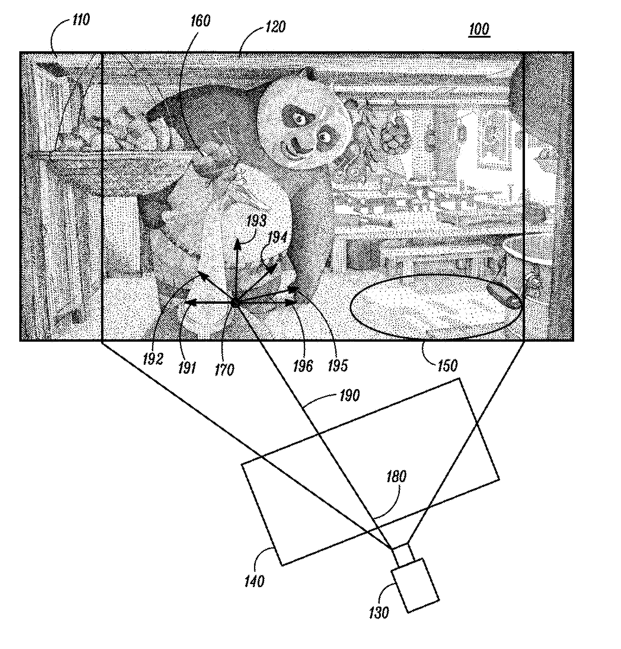
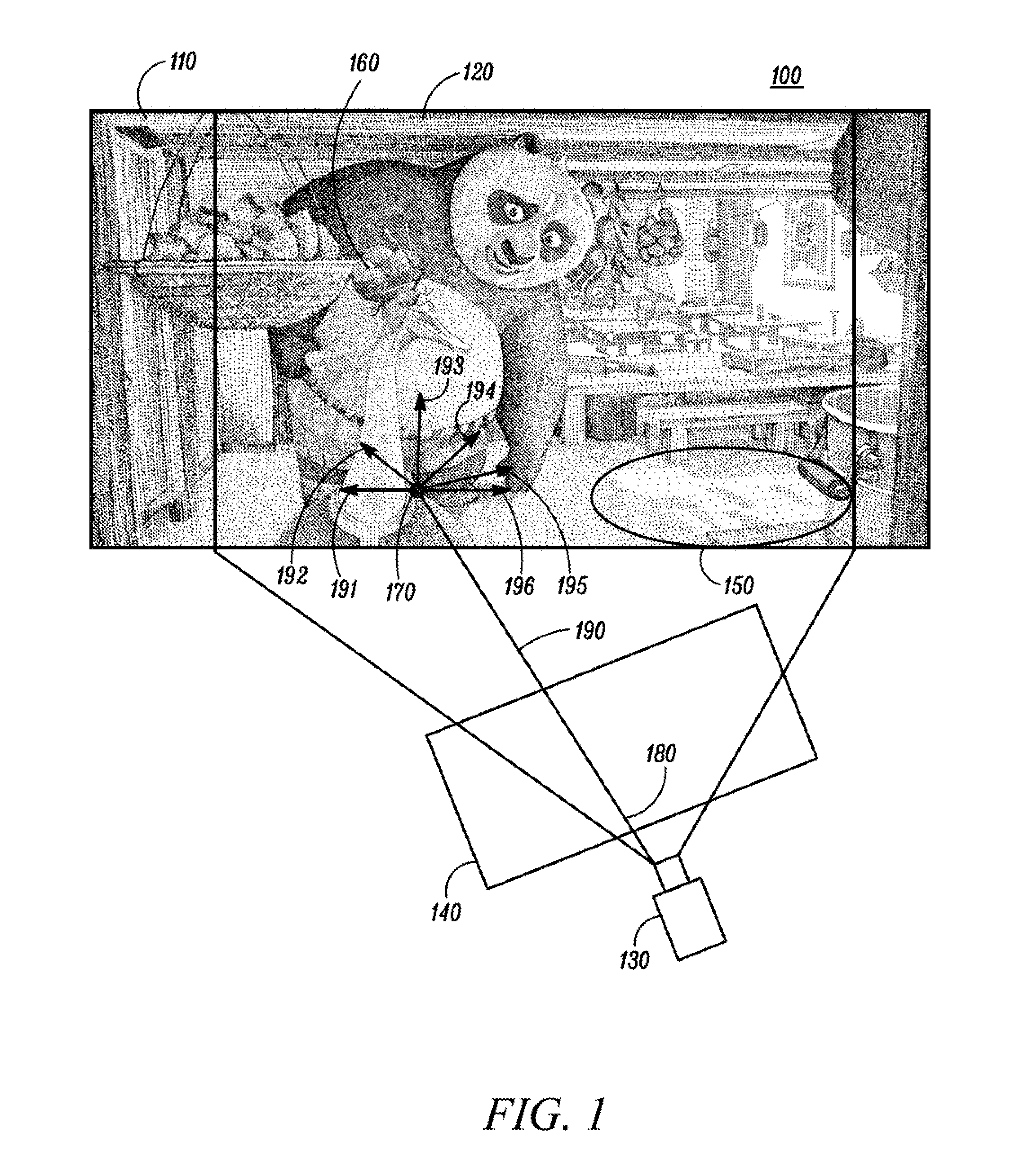
[0023]FIG. 1 illustrates an exemplary scene 100 lit by indirect lighting 150. The scene 100 may be a snapshot taken by a virtual camera 130, viewing a virtual world 110. The box 120 highlights the portion of the virtual world 110 that may be visible to the virtual camera 130. Indirect lighting 150 may be light from an out-of-view light source, such as a light bulb, the sun, or the like. The scene 100 may be rendered using a conventional ray tracing engine.

[0024]A snapshot of a scene 100 using a ray tracing approach may be rendered by calculating the path of rays from a virtual camera 130 through pixels in an image plane 140 and then into the virtual world 110. For example, consider ray 190. R...


PUM


Abstract

A computer-animated scene illuminated by indirect light is shaded. The scene is comprised of sample locations on a surface element of an object in the scene. A point cloud representation of the scene is generated. Optionally, an importance map of the scene, based on the point cloud representation, is generated. The importance map is generated by rasterizing one or more points in the point cloud and designating areas of interest based on the energy value of the one or more points in the point cloud. A ray tracing engine is biased, based on the importance map. The biased ray tracing engine calculates the path of the ray to the sample locations in the scene to an area of interest. The scene is shaded using the output from the biased ray tracing engine.

Description

BACKGROUND[0001]1. Field[0002]This application relates generally to computer graphics, and more specifically to computer systems and processes for efficiently rendering a scene illuminated by indirect light using ray tracing.[0003]2. Related Art[0004]Rendered images used in high quality motion pictures need to be of high quality. Global illumination is a technique used in computer graphics to add more realistic lighting to the scenes. Global illumination takes into account not only the light that comes directly from the light sources placed in the scene (direct illumination), but also light rays that are reflected by other surfaces in the scene (indirect illumination). For example, with direct illumination alone, shadows appear black, because there is no direct illumination in the shadowed areas. By contrast, global illumination allows light to bounce around in the scene before it is finally reflected towards the virtual camera. As a result, details in the shadowed areas may be seen...

Claims


Application Information

Patent Timeline
Patent Type & Authority Applications(United States)
IPC IPC(8): G06T15/60
CPCG06T15/06G06T2210/56G06T17/00G06T15/50
Inventor ARMSDEN, CHRIS F.TARTAGLIA, BRUCE
Owner DREAMWORKS ANIMATION LLC
Why Eureka
Try Eureka