
System and method for automated fault control and restoration of smart grids

a smart grid and fault control technology, applied in emergency protective circuit arrangements, instruments, data processing applications, etc., can solve problems such as unsatisfactory fault isolation, large number of consumers experiencing service outages, and delay in detection of faults at distribution devices located nearer locations

Inactive Publication Date: 2013-01-03
GENERAL ELECTRIC CO
View PDF9 Cites 96 Cited by
  • Summary
  • Abstract
  • Description
  • Claims
  • Application Information

AI Technical Summary

Benefits of technology

This patent describes a system that helps to protect power networks. It includes multiple devices that communicate with each other and a controller that receives information about the communication channels from these devices. Based on this information, the controller calculates the time it takes for a signal to travel between devices in the network. It also determines indicators of reliability for each device, which measure how reliable the communication is. The controller then adjusts the response characteristics of the devices to minimize these indicators. In simple terms, this system helps to make power networks safer and more reliable.

Problems solved by technology

The physical effects of communication channels such as shadowing and multipath propagation for example leads to delay in detection of faults that occur at the distribution devices located nearer to the substation.
The delay in detection of the fault results in less than optimal isolation of faults, undue equipment stress, and a larger than necessary number of consumers experiencing service outages during the faults.

Method used


Image

  • System and method for automated fault control and restoration of smart grids
  • System and method for automated fault control and restoration of smart grids
  • System and method for automated fault control and restoration of smart grids

Examples


Embodiment Construction

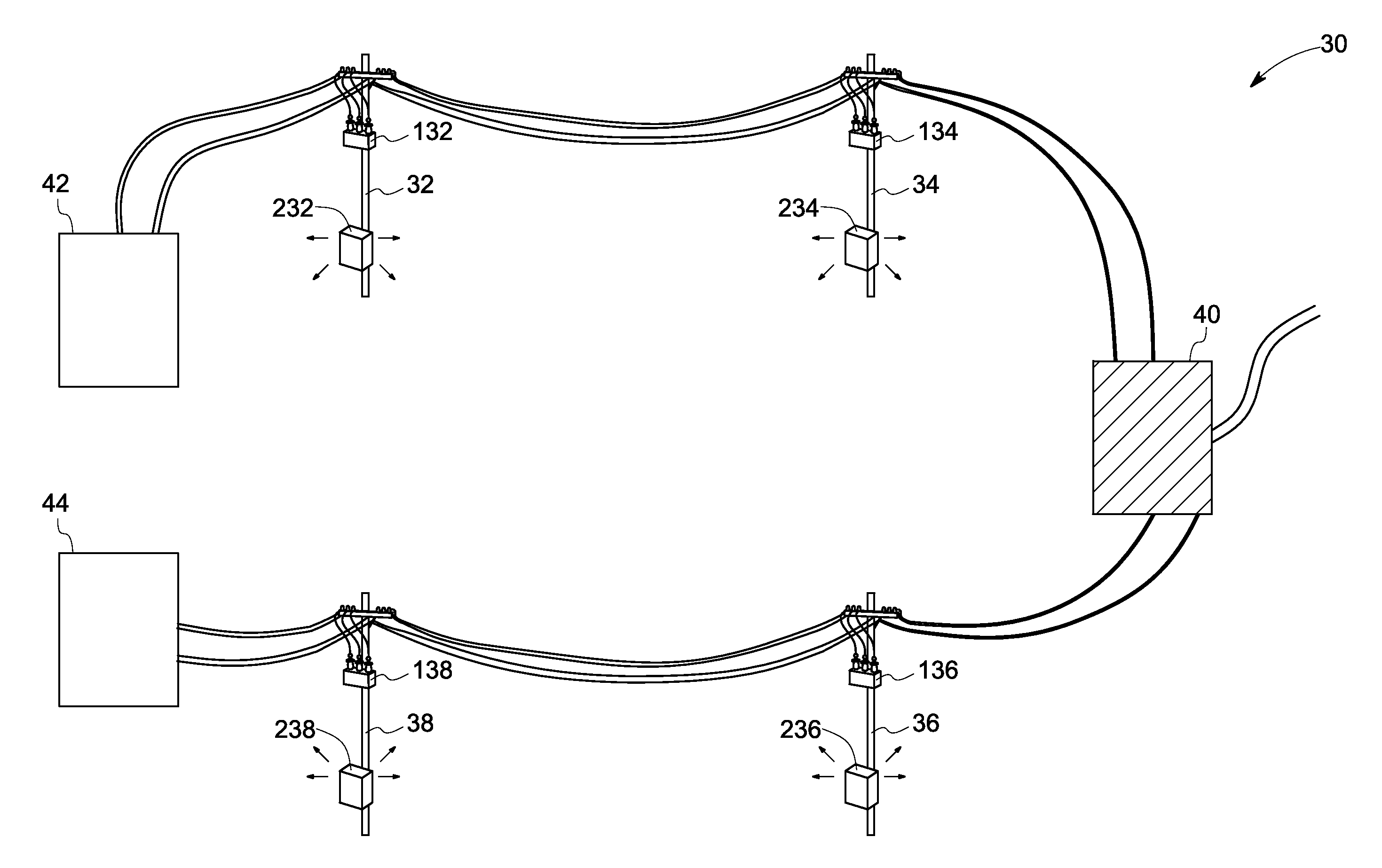
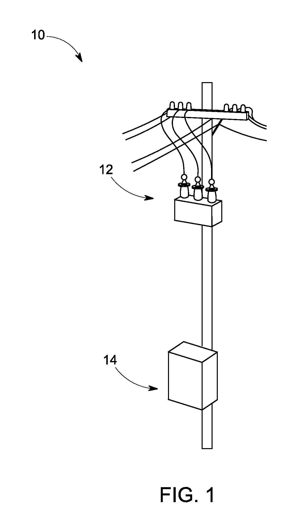
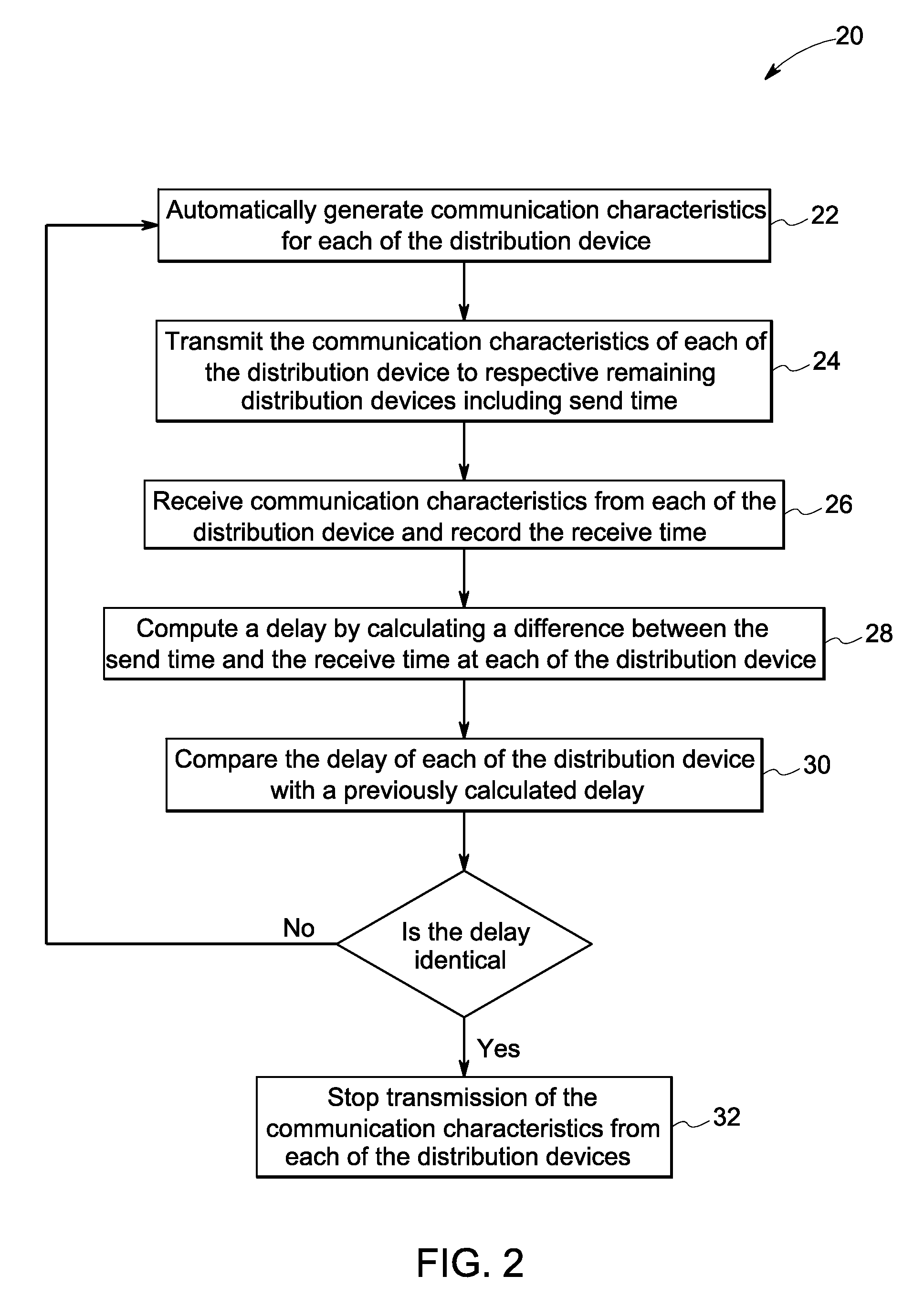
[0013]Embodiments of the present invention include a system and method for self-organizing protection coordination system within a power network. The power network includes a plurality of distribution devices communicatively coupled to each other that receive communication channel characteristics from each of the distribution devices in the power network. Each of the distribution devices includes a controller coupled to the distribution devices that computes a delay in time for receiving the communication channel characteristics from the plurality of distribution devices in the power network. The controller determines reliability indicators for each of the distribution devices and adjusts tripping characteristics of the distribution devices based on the delay to maximize reliability and minimize outage time and customers impacted.

[0014]Generally, power networks include multiple distribution devices electrically coupled to each other. Each of the distribution devices includes a prote...


PUM


Abstract

A self-organizing protection coordination system within a power network is provided. The self-organizing protection coordination system in the power network includes a plurality of distribution devices communicatively coupled to each other in a power network. The power network also includes a protection device coupled to each of the plurality of distribution devices configured to transmit power in the distribution network. The power network further includes a controller coupled to each of the plurality of distribution devices. The controller receives communication channel characteristics from a plurality of distribution devices in a distribution network at an interval of time. The controller also computes a delay in time for receiving the communication characteristics. The controller further determines a plurality of reliability indicators at each of the plurality of distribution devices. The controller adjusts tripping characteristics of the plurality of distribution devices to minimize the reliability indicators based on the computed delay.

Description

BACKGROUND[0001]A smart grid delivers electricity to consumers while leveraging digital communication and control technologies to minimize financial cost, save energy, and increase reliability. If designed properly, the smart grid will have a significant impact on improving a wide range of aspects in the electric power generation and distribution industry. Examples include self-healing, high-reliability, resistance to cyber-attack, accommodation of a wide variety of types of distributed generation and storage mechanisms, optimized asset allocation, and minimization of operation and maintenance expenses as well as high-resolution market control that incorporates advanced metering and demand-response.[0002]An important component in operation of smart grids is fault detection, isolation, and restoration of the smart grid. Today, most distribution devices do not communicate with each other but operate and detect faults independently, unaware of the state of other protection devices and ...

Claims


Application Information

Patent Timeline
IPC IPC(8): H02H7/00
CPCG06Q50/06H02H7/261H02H3/0935H02H3/006
Inventor BUSH, STEPHEN FRANCISMAHONY, MICHAEL JOSEPH
Owner GENERAL ELECTRIC CO
Learn More