FPGA-based modularization double-joint servo control system
A servo control system and double-joint technology, applied in the field of robotics, can solve problems such as low integration, complex robot structure, and bulky volume, and achieve the effects of high reliability, improved applicability and stability, and miniaturized reliability
- Summary
- Abstract
- Description
- Claims
- Application Information
AI Technical Summary
Problems solved by technology
Method used
Image
Examples
specific Embodiment approach 1
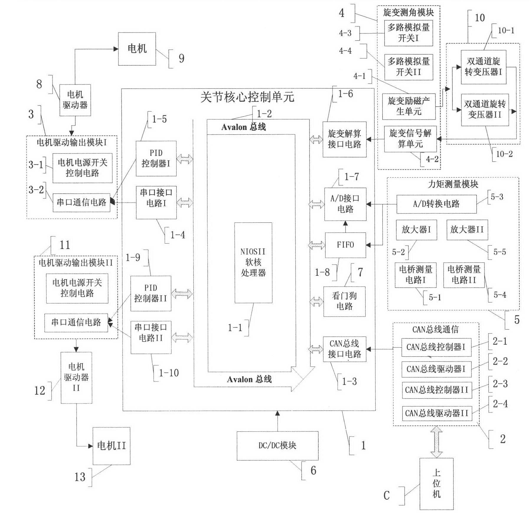
[0012] Specific implementation mode one: According to the instructions attached figure 1 Describe this embodiment in detail. The FPGA-based modular dual-joint servo control system described in this embodiment includes a joint core control unit 1, a CAN bus communication module 2, a motor drive output module 3, a resolver angle measurement module 4, a torque Measurement module 5, DC / DC module 6, joint core control unit 1 includes NIOSII soft-core processor 1-1, Avalon bus 1-2, CAN bus interface circuit 1-3, resolver interface circuit 1-6, A / D interface circuit 1-7, FIFO1-8, CAN bus communication module 2 includes CAN bus controller I2-1 and bus driver I2-2, motor drive module 3 includes motor power switch control circuit 3-1 and serial port communication circuit 3 -2, the torque measurement module 5 includes a bridge measurement circuit 5-1, an amplifier 5-2, and an A / D conversion circuit 5-3; the upper computer C communicates with the joint core control unit 1 through the CAN...
specific Embodiment approach 2
[0016] Embodiment 2. The difference between this embodiment and Embodiment 1 is that the joint controller realizes the control of the double joints. CAN bus communication module 2 also includes CAN bus controller I2-1 and CAN bus driver I2-2, each joint contains a CAN bus controller and driver, and the host computer selects different joint channels by sending data to realize dual-joint control.
[0017] In this specific embodiment, the resolver angle measurement module 4 also includes a multi-channel analog switch I4-3 and a multi-channel analog switch II4-4, and the dual-channel resolver 10 also includes a dual-channel resolver II 10-2, Each joint contains a dual-channel resolver. The resolver angle measurement module 4 forms two independent paths through a resolver resolver in the resolver unit 4-2 and a multi-channel analog switch I4-3 or a multi-channel analog switch II4-4, each Each channel can complete the signal calculation of the resolver precision machine and the ro...
specific Embodiment approach 3
[0021] Embodiment 3. The difference between this embodiment and Embodiments 1 and 2 is that a watchdog circuit 7 is added and integrated on the FPGA chip. The watchdog is essentially a timer circuit. The setting of the watchdog is carried out in two steps, including initializing the dog and feeding the dog, which is realized by software operation. The dog is initialized after the system parameters are initialized, and the dog is fed to the main control cycle module. When the software is not working properly, the timer will not work properly. If the dog feeding operation is interrupted within the specified period, the system will automatically reset.
[0022] In this specific embodiment, the watchdog module is added in the software to monitor the operation of the software. When the software is not running normally, the system will automatically reset and resume normal work, preventing the program from infinitely looping, increasing the reliability and reliability of the system...
PUM
 Abstract
Description
Claims
Application Information
 - R&D
- Intellectual Property
- Life Sciences
- Materials
- Tech Scout
- Unparalleled Data Quality
- Higher Quality Content
- 60% Fewer Hallucinations
Browse by: Latest US Patents, China's latest patents, Technical Efficacy Thesaurus, Application Domain, Technology Topic, Popular Technical Reports.
© 2025 PatSnap. All rights reserved.Legal|Privacy policy|Modern Slavery Act Transparency Statement|Sitemap|About US| Contact US: help@patsnap.com


