Breaker box powerline communication device

Inactive Publication Date: 2013-01-03
AVAGO TECH WIRELESS IP SINGAPORE PTE
View PDF6 Cites 233 Cited by
  • Summary
  • Abstract
  • Description
  • Claims
  • Application Information

AI Technical Summary

Problems solved by technology

In many structures, however, the power mains, which service multiple differing dwellings, offices, etc., are serviced by a common feed, which allows PLC signals to p

Method used


Image

  • Breaker box powerline communication device
  • Breaker box powerline communication device
  • Breaker box powerline communication device

Examples


Embodiment Construction

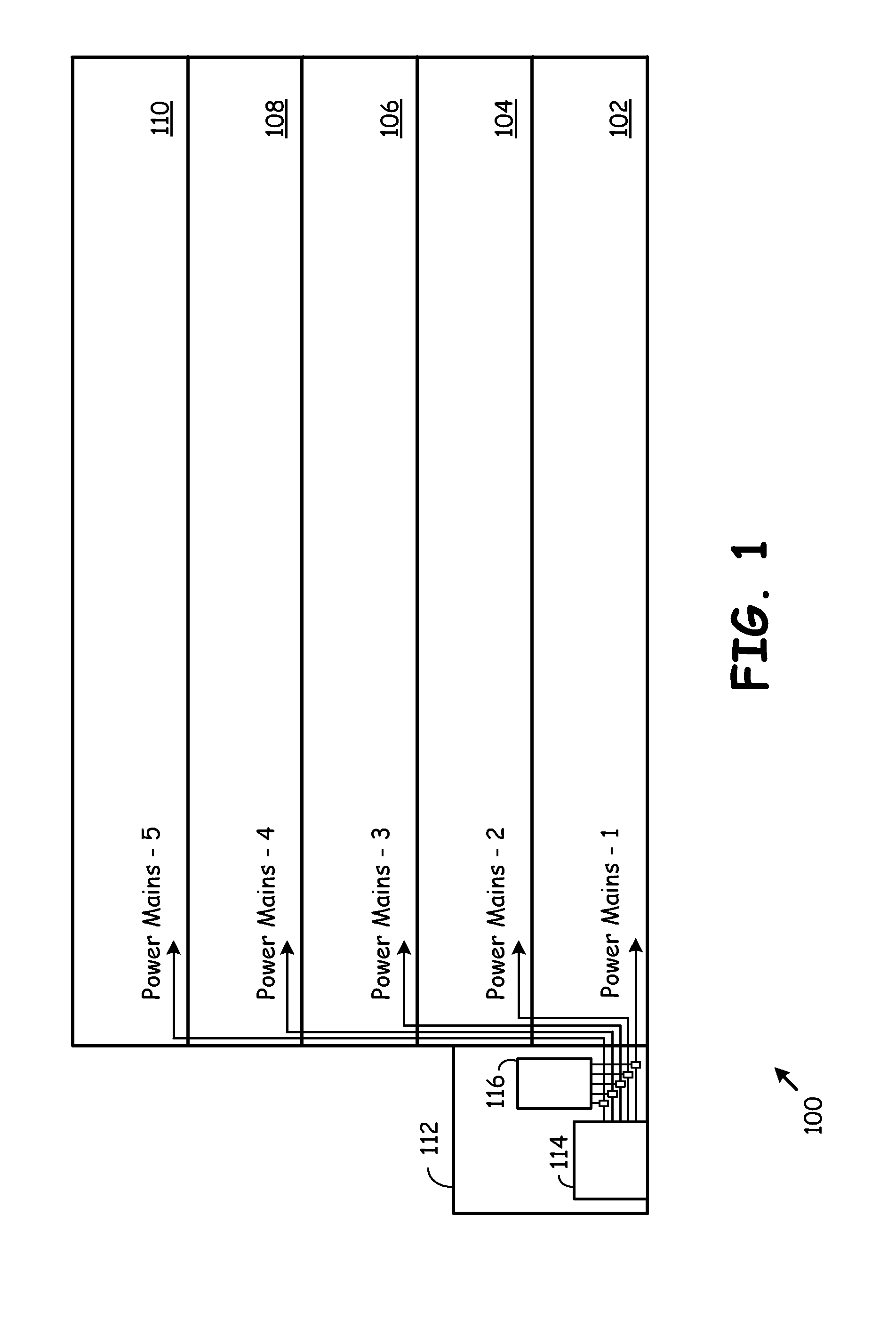
[0022]FIG. 1 is a system diagram illustrating a multiple unit complex serviced by a breaker box Powerline Communication (PLC) device constructed according to one or more embodiments of the present invention. The multiple unit complex 100 may be an apartment complex, an office building, a shopping mall, or another type of building that is subdivided on the basis of workers, inhabitants, or upon another basis. The complex 100 is subdivided into a number of floors, spaces, offices, segments, etc., indicated as 102, 104, 106, 108, and 110. Each of these spaces 102-110 is serviced by a respective power main, e.g., power mains 1-5, respectively. These spaces 102-110 may also be simply referred to as having separate power mains service and may not correspond to a physical division of a space.

[0023]The complex 100 is serviced by a power distribution device 114, which may be a breaker box, fuse box, or another type of device that services the power mains 1-5. The power distribution device 11...


PUM


Abstract

A Power Line Communications (PLC) device includes a processing module, memory, and a plurality of PLC communication interfaces coupled to the processing module. Each PLC communication interface couples to a respective PLC media segment. The processing module, the plurality of PLC communication interfaces, and the memory are operable to receive a PLC communication from a first PLC device via a first PLC communication interface of the plurality of communication interfaces, process the PLC communication to identify a second PLC device, and transmit the PLC communication to the second PLC device via a second PLC communication interface of the plurality of communication interfaces. The PLC device may include one or more non-PLC interfaces that support non-PLC communications.

Description

CROSS-REFERENCE TO PRIORITY APPLICATION[0001]This application claims priority under 35 U.S.C. §119(e) to U.S. Provisional Application Ser. No. 61 / 503,060 filed Jun. 30, 2011, which is incorporated herein by reference in its entirety.BACKGROUND OF THE INVENTION[0002]1. Field of the Invention[0003]The present invention relates to powerline communications and in particular, powerline communication devices, and systems of use therefore.[0004]2. Description of the Related Art[0005]With the growing need for the exchange of digital content (e.g. MP3 audio, MPEG4 video and digital photographs) there is a widely recognized need to improve digital communication systems. Powerline communication (PLC) is a technology that encodes data in a signal and transmits the signal on existing electricity powerlines in a band of frequencies that are not used for supplying electricity. Accordingly, PLC leverages the ubiquity of existing electricity networks to provide extensive network coverage. Furthermor...

Claims


Application Information

Patent Timeline
IPC IPC(8): H04B3/54
CPCH04W36/14H04L25/02H03M1/124H04W76/026H04W76/16
Inventor BENNETT, JAMES D.
Owner AVAGO TECH WIRELESS IP SINGAPORE PTE
Why Eureka
Try Eureka