
Power Line Communications Coupling Device and Method

a technology of power line and coupling device, which is applied in the field of power line coupling device and method, can solve the problems of impeded high frequency signals, power lines are not designed to provide high speed data communication, and difficulties to overcom

Inactive Publication Date: 2009-04-02
CURRENT TECH
View PDF99 Cites 238 Cited by
  • Summary
  • Abstract
  • Description
  • Claims
  • Application Information

AI Technical Summary

Benefits of technology

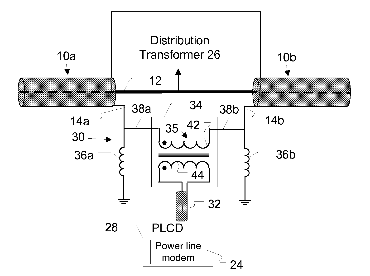
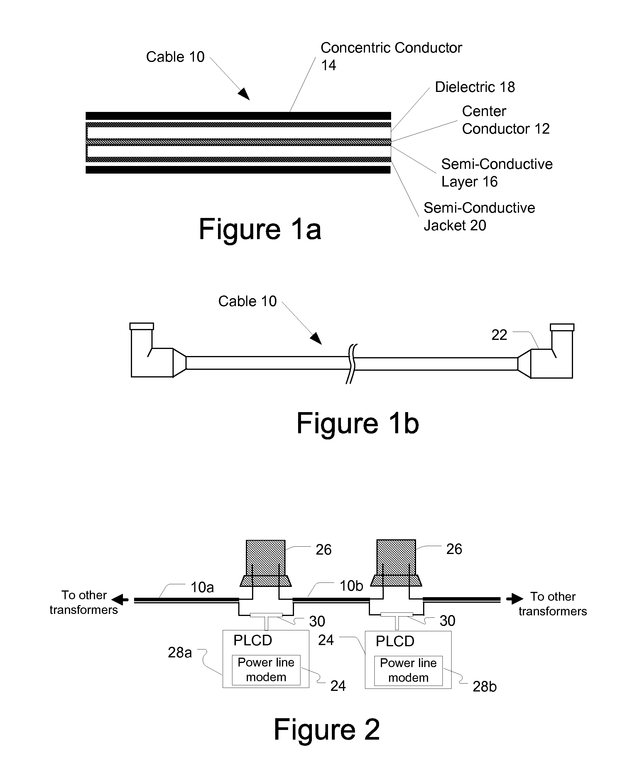
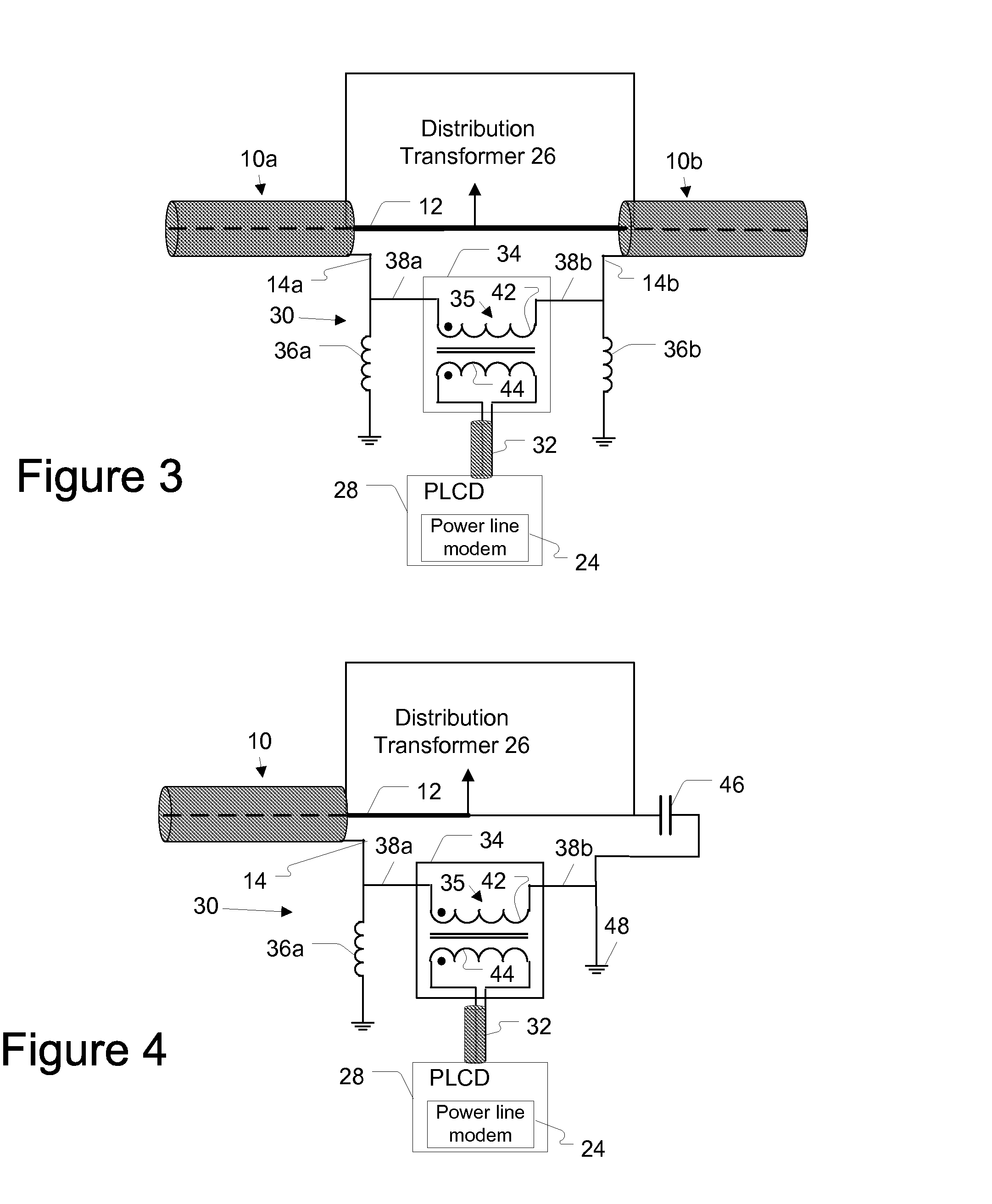
[0007]The present invention provides a method and device for providing communications via one or more underground power lines. Underground power lines may comprise a plurality of segments disposed in series with each other and carrying a power having a voltage greater than one thousand volts on an internal conductor, and wherein each segment is coaxial in structure and includes a neutral conductor. In one embodiment, the device may comprise a first inductor having a first end connected to a first node and a second end connected to ground, a second inductor having...

Problems solved by technology

There are many challenges to overcome when using power lines for data communication.
A transformer passes the low frequency signals (e.g., the 50 or 60 Hz power signals) but impedes impeding the high frequency signals (e.g., frequencies typically used for data communication).
As such, many power line communication systems face the challenge of communicating the data signals around, or through, the distribution transformers.
Another challenge is that power lines are not designed to provide high speed data communications, and are susceptible to interference and signal losses.
It has been found that the URD MV power line cables are very lossy at frequencies used to provide broadband communications.

Method used


Image

  • Power Line Communications Coupling Device and Method
  • Power Line Communications Coupling Device and Method
  • Power Line Communications Coupling Device and Method

Examples


Embodiment Construction

[0027]In the following description, for purposes of explanation and not limitation, specific details are set forth, such as particular networks, communication systems, computers, terminals, devices, components, techniques, PLCS, data and network protocols, software products and systems, enterprise applications, operating systems, development interfaces, hardware, etc. in order to provide a thorough understanding of the present invention.

[0028]However, it will be apparent to one skilled in the art that the present invention may be practiced in other embodiments that depart from these specific details. Detailed descriptions of well-known networks, communication systems, PLCS, computers, terminals, devices, components, techniques, data and network protocols, software products and systems, operating systems, development interfaces, and hardware are omitted so as not to obscure the description of the present invention.

Communications Coupling Device and Power Line Cable

[0029]According to ...


PUM


Abstract

A method and device for providing communications via one or more underground power lines is provided. Underground power lines may comprise a plurality of segments disposed in series with each other and carrying a power having a voltage greater than one thousand volts on an internal conductor, and wherein each segment is coaxial in structure and includes a neutral conductor. In one embodiment, the device may comprise a first inductor having a first end connected to a first node and a second end connected to ground, a second inductor having a first end connected a second node and a second end connected to ground, and a transformer having a first winding having a first end and a second end. The first node may be connected to a neutral conductor of a first segment of the power line and to the first end of the first winding of said transformer. The second node may be connected to a neutral conductor of a second segment of the power line and to the second end of the first winding of said transformer. The transformer comprises a second winding configured to be communicatively coupled to a communication device.

Description

FIELD OF THE INVENTION [0001]The present invention generally relates to power line coupling devices and methods, and more particularly to a device and method for coupling a broadband power line communication device to an insulated medium voltage power line, such as an underground residential distribution power line.BACKGROUND OF THE INVENTION [0002]The need for reliable broadband communication networks to deliver data services such as voice over internet protocol (VoIP), video, internet web data, email, file sharing, stereo over IP, and other such services is increasing. In response to these demands, the communication infrastructure is expanding to include many types of communication networks beyond the public switched telephone network. A power line communication system (PLCS) is an example of a communication network in the expanding communication infrastructure.[0003]A PLCS uses portions of the power system infrastructure to create a communication network. In addition to carrying ...

Claims


Application Information

Patent Timeline
IPC IPC(8): G08B1/08
CPCH04B3/56H04B2203/5491H04B2203/5445
Inventor RADTKE, WILLIAM O.
Owner CURRENT TECH
Learn More