
Power line communication device and method

a technology of power line communication and communication device, which is applied in the direction of frequency-division multiplex, electric controller, instruments, etc., can solve the problems of reducing the overall data rate, affecting the efficiency of infrastructure utilization, so as to facilitate communication

Inactive Publication Date: 2010-09-14
CHEMTRON RES
View PDF79 Cites 239 Cited by
  • Summary
  • Abstract
  • Description
  • Claims
  • Application Information

AI Technical Summary

Benefits of technology

"The present invention is a device and method for communication over a low voltage power line between a user device and an external power line communication device. The device includes a communication module and a controller that can switch between configurations based on the data rate, error rate, or noise detection. The device can also transmit utility data to the power line communication device. The technical effect of this invention is to enable efficient and reliable communication over low voltage power lines and to improve the reliability and accuracy of data transmission."

Problems solved by technology

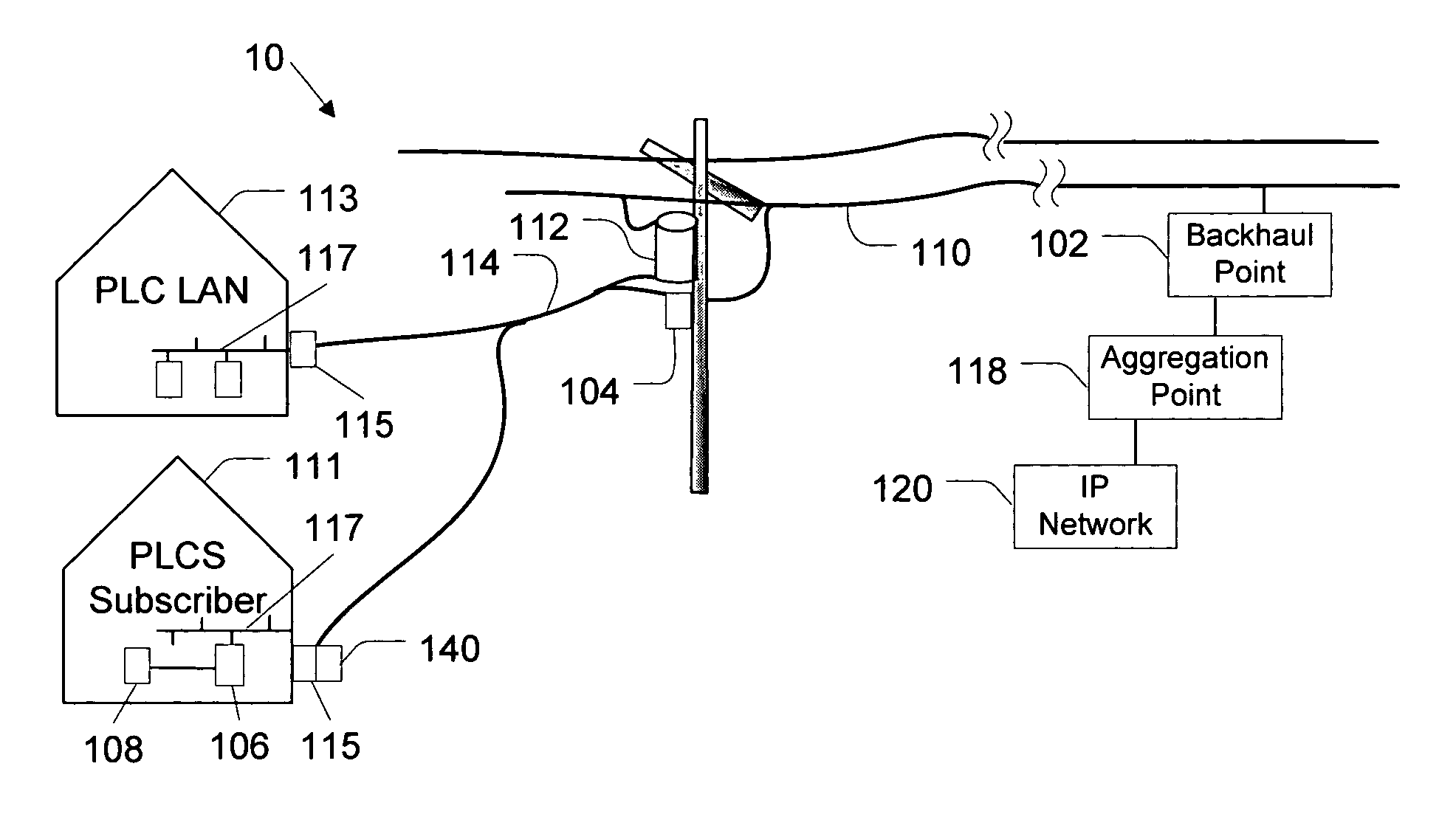
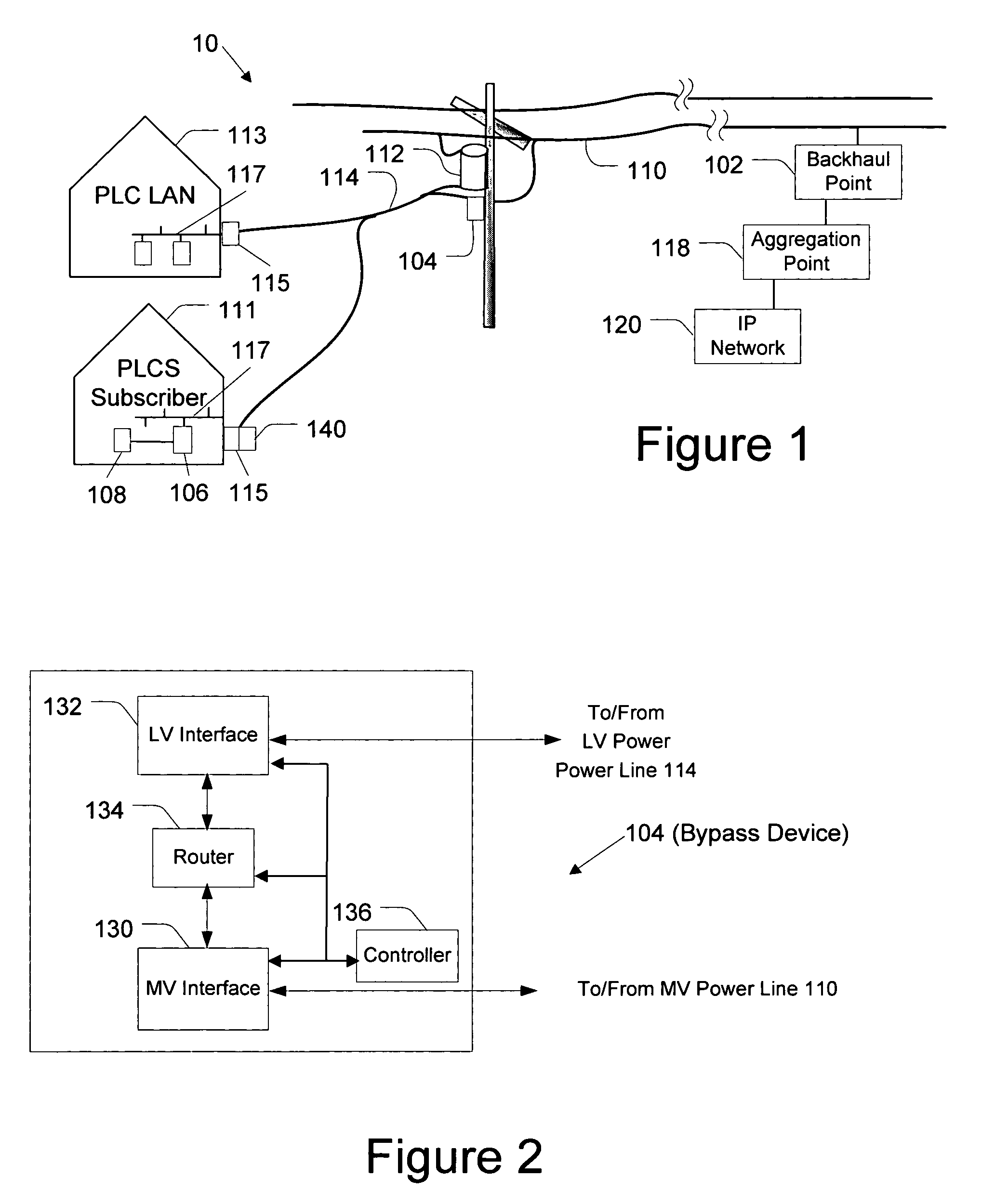
Thus, the internal low voltage power lines may carry PLC LAN signals, which undesirably may propagate onto external low voltage power lines.
A potential problem occurs when non-subscriber PLC LAN signals and subscriber PLCS data signals are in the same frequency band and arrive at the bypass device at an overlapping time period.
Thus, the PLC LAN data signals may degrade or even prohibit the upstream PLCS communications from the PLCS subscriber premises.
However, because repeating may sometimes cause latency and lower the overall data rate, they can be undesirable in many applications, which may include communicating video data, telephony data, and other latency sensitive and / or data rate sensitive applications.
Additionally, repeating all data (e.g., upstream and downstream), when satisfactory communications may be achieved without such repeating, may not provide efficient utilization of the infrastructure.

Method used


Image

  • Power line communication device and method
  • Power line communication device and method
  • Power line communication device and method

Examples


Embodiment Construction

[0017]In the following description, for purposes of explanation and not limitation, specific details are set forth, such as particular networks, communication systems, computers, terminals, devices, components, techniques, data and network protocols, software products and systems, PLCS, enterprise applications, operating systems, development interfaces, hardware, etc. in order to provide a thorough understanding of the present invention.

[0018]However, it will be apparent to one skilled in the art that the present invention may be practiced in other embodiments that depart from these specific details. Detailed descriptions of well-known networks, PLCS, communication systems, computers, terminals, devices, components, techniques, data and network protocols, software products and systems, operating systems, development interfaces, and hardware are omitted so as not to obscure the description of the present invention.

[0019]One example of a portion of a PLCS 10 is shown in FIG. 1, which ...


PUM


Abstract

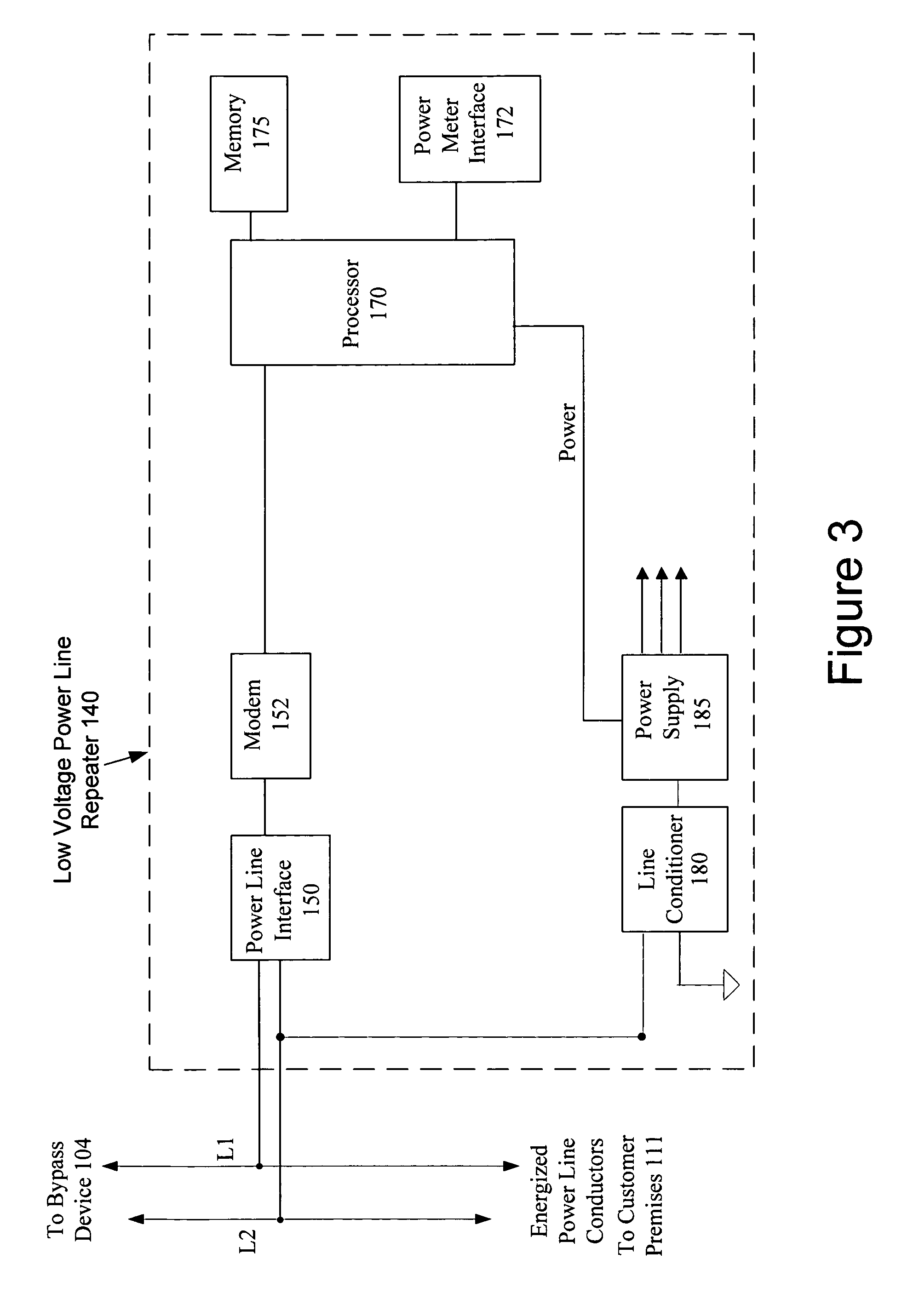
A power line communication device configured to facilitate communications over a low voltage power line between a downstream user device and an external power line communication device is provided. In one embodiment, the device may include a communication module configured to communicate over a low voltage power line and a controller configured to control the module. The controller is configured to operate the module in a first configuration in which all repeating is disabled; and a second configuration wherein upstream repeating is enabled and downstream repeating is disabled. The controller may transition from the first configuration to the second configuration in response to a command received via the low voltage power line or upon determining that a triggering event has been detected such as an unacceptable data rate, error rate, or noise detection. In some embodiments, the device may form part of a utility meter and also transmit utility data to the power line communication device.

Description

FIELD OF THE INVENTION[0001]The present invention generally relates to methods and systems of power line data communication systems, and more particularly to power line communications over low voltage power lines.BACKGROUND OF THE INVENTION[0002]Using the power system infrastructure to deliver data communication services is becoming increasingly viable. For example, commercial services are available in many areas for delivering broadband internet access over the power lines. Power line communication system (PLCS) communications, such as broadband communications, may be communicated over medium voltage power lines. Repeating devices may receive the communications and transmit the communications further along the medium voltage power lines. To avoid signal deterioration at distribution transformers along the power line pathways, bypass devices may be coupled to the medium voltage power lines near transformers. The bypass device may communicate with user devices via low voltage power l...

Claims


Application Information

Patent Timeline
Patent Type & Authority Patents(United States)
IPC IPC(8): H04Q1/30G08B1/08H04M11/04
CPCH04B3/54H04B3/58H04B2203/5479
Inventor BERKMAN, WILLIAM H.
Owner CHEMTRON RES
Learn More