Display device, control system, and storage medium storing control program

Active Publication Date: 2013-01-03
KYOCERA CORP
View PDF5 Cites 21 Cited by
  • Summary
  • Abstract
  • Description
  • Claims
  • Application Information

AI Technical Summary

Benefits of technology

The patent describes a display device that can show a 3D image of a bunch of cubes arranged in three directions perpendicular to each other. The device can detect moves of objects in the 3D space and change the position of each cube accordingly. This makes the image appear to move or be reshaped in response to the user's movements. The device can be controlled by a mobile device with a touch screen or a control device. The technical effect of this patent is to provide a new and immersive way to view and interact with 3D images.

Problems solved by technology

The three-dimensional display is a user-friendly display form; however, it is used just for viewing purposes, and is not used for improving the convenience of operations.
Although there are applications for 3D games such as three-dimensional puzzles, a selection is made only for each specific single object using an operation button or so, and therefore it takes more time for users to get used to operations.

Method used


Image

  • Display device, control system, and storage medium storing control program
  • Display device, control system, and storage medium storing control program
  • Display device, control system, and storage medium storing control program

Examples


first embodiment

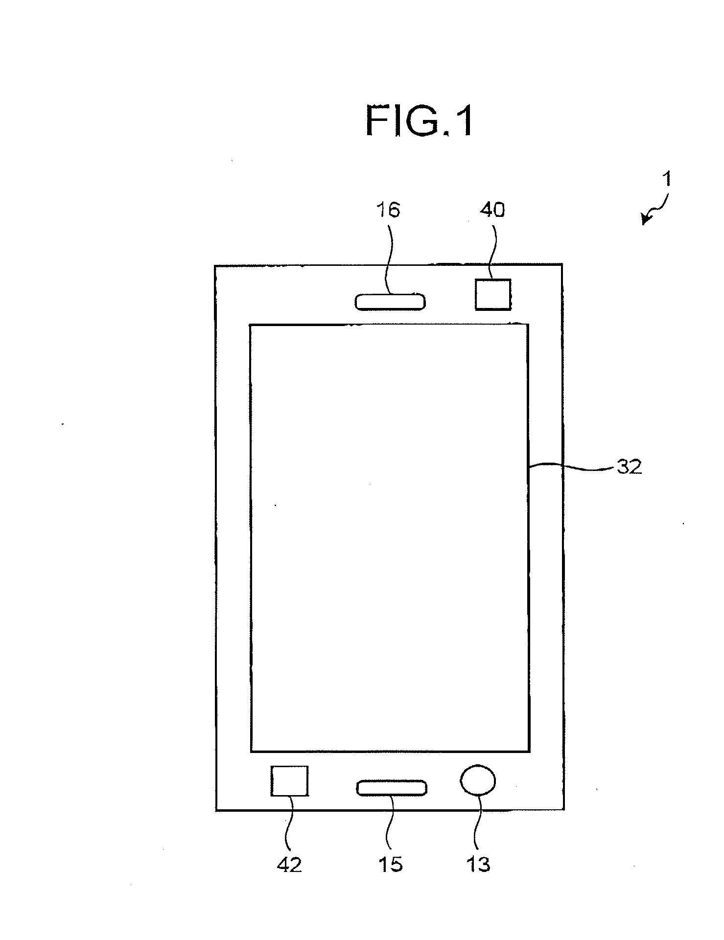
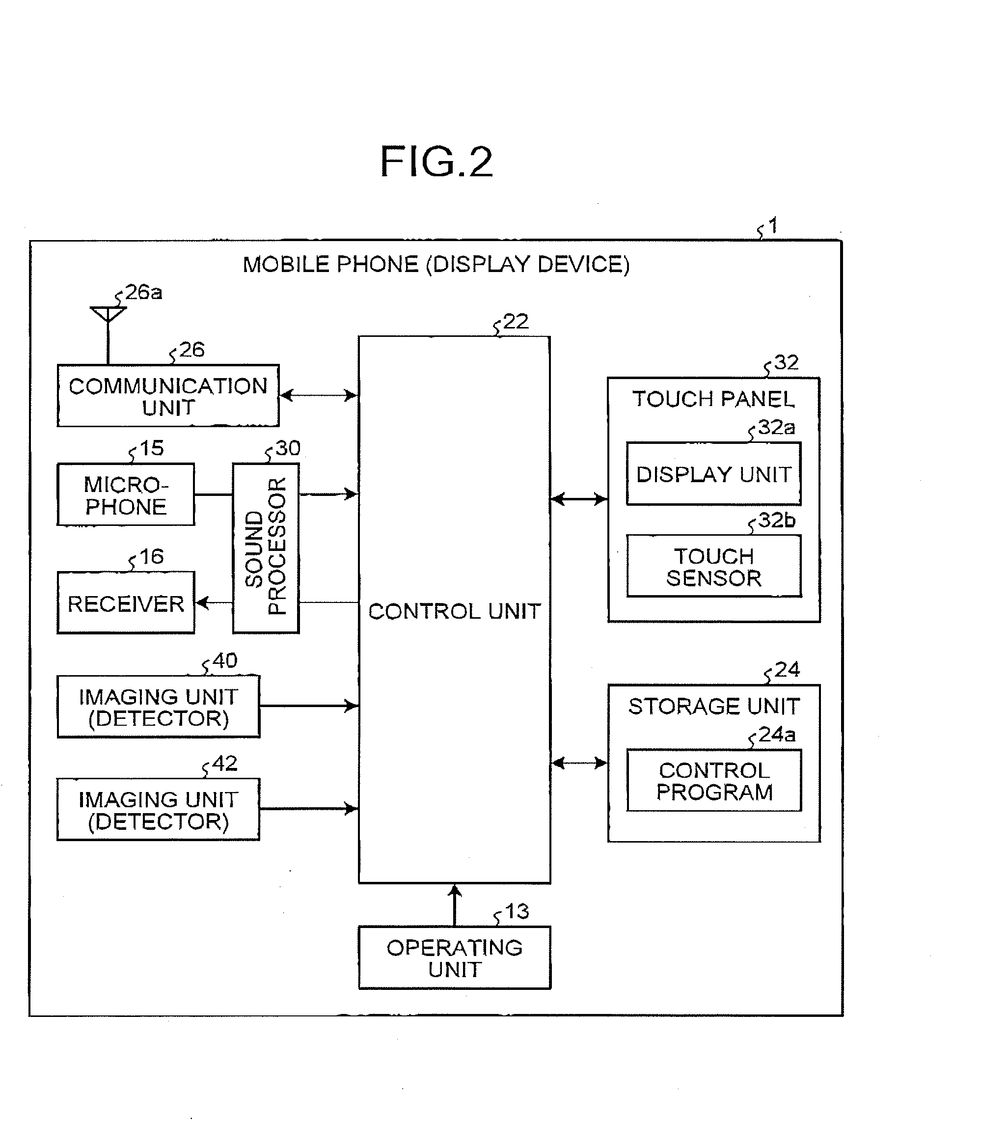
[0045]First of all, a configuration of a mobile phone (display device) 1 is explained below with reference to FIG. 1 and FIG. 2. FIG. 1 is a front view of the mobile phone 1. FIG. 2 is a block diagram of the mobile phone 1.

[0046]As illustrated in FIG. 1 and FIG. 2, the mobile phone 1 includes an operating unit 13, a microphone 15, a receiver 16, a control unit 22, a storage unit 24, a communication unit 26, a sound processor 30, a touch panel 32, an imaging unit 40, and an imaging unit 42. Respective parts of the operating unit 13, the microphone 15, the receiver 16, the touch panel 32, and the imaging units 40 and 42 are exposed to the front surface of the mobile phone 1.

[0047]The operating unit 13 has physical buttons, and outputs a signal corresponding to a pressed button to the control unit 22. In the example illustrated in FIG. 1, the operating unit 13 has only one button, however, may have a plurality of buttons.

[0048]The microphone 15 acquires an external sound. The receiver...

second embodiment

[0148]As explained above, the second embodiment is configured to select the three-dimensional object when the three-dimensional object is located at the position between the objects such as the fingers and then the distance between the objects is maintained substantially constant for a longer period of time than the predetermined time. Therefore, the user can quickly start a subsequent operation after the three-dimensional object is selected.

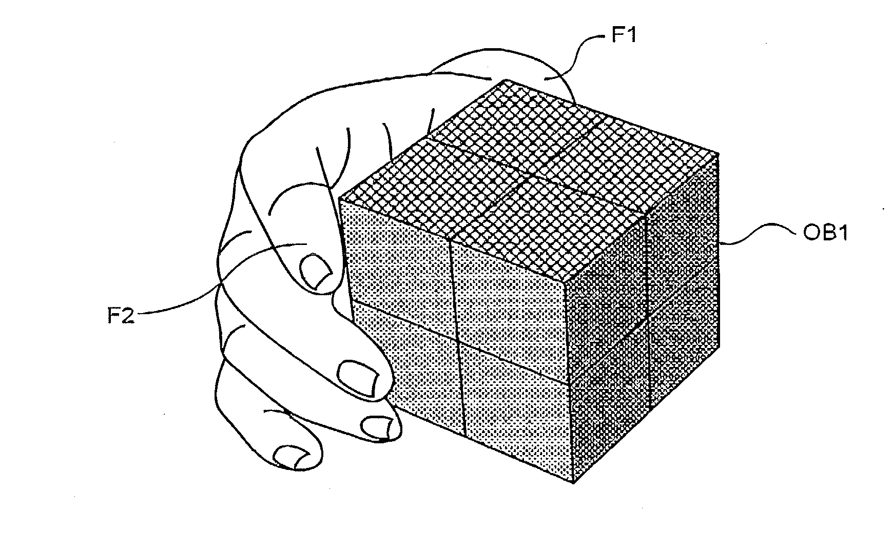
[0149]As illustrated at Step S31 to Step S33 in FIG. 19, a state, in which at least one of the first object and the second object is brought into contact with the three-dimensional object and then the distance between the first object and the second object is maintained substantially constant for a longer period of time than the predetermined time, may be set as the condition for selecting the three-dimensional object. FIG. 19 is a diagram for explaining another example of how to detect an operation performed for the three-dimensional object. If...

third embodiment

[0192]As explained above, the third embodiment is configured to change the three-dimensional object according to the operation from the time when it is detected that the three-dimensional object is located between the objects such as the fingers, and therefore the user can easily recognize the selection of the three-dimensional object.

[0193]As illustrated at Step S61 to Step S63 in FIG. 25, a state, in which at least one of the first object and the second object is brought into contact with the three-dimensional object and then the distance between the first object and the second object is maintained substantially constant for a longer period of time than the predetermined time, may be set as the condition for selecting the three-dimensional object. FIG. 25 is a diagram for explaining another example of how to detect an operation performed for the three-dimensional object. If a plurality of three-dimensional objects are closely displayed, by setting the contact with the three-dimens...


PUM


Abstract

According to an aspect, a display device includes a display unit, a detecting unit, and a control unit. The display unit stereoscopically displays an aggregation of a plurality of cubes in three-dimensional space. The cubes are arranged along three directions perpendicular to one another. The detecting unit detects moves of objects in the three-dimensional space. The control unit changes a location of each of the cubes according to a detection result of the detecting unit.

Description

CROSS-REFERENCE TO RELATED APPLICATIONS[0001]This application claims priority from Japanese Application No. 2011-143342, filed on Jun. 28, 2011, the content of which is incorporated by reference herein in its entirety.BACKGROUND OF THE INVENTION[0002]1. Technical Field[0003]The present disclosure relates to a display device, a control system, and a storage medium storing therein a control program.[0004]2. Description of the Related Art[0005]Some display devices with a display unit such as mobile phones can stereoscopically display an image and so on (see e.g., Japanese Patent Application Laid-Open No. 2011-95547). The three-dimensional (3D) display is implemented by using binocular disparity.[0006]In addition, there are gaming devices capable of executing applications of three-dimensional games (see e.g., Japanese Patent Application Laid-Open No. 2011-101677). For example, the gaming device described in Japanese Patent Application Laid-Open No. 2011-101677 executes a 3D game using a...

Claims


Application Information

Patent Timeline
IPC IPC(8): A63F9/24A63F13/213A63F13/214A63F13/2145A63F13/428A63F13/52A63F13/55
CPCA63F9/0826A63F13/005A63F2300/8094A63F2300/1087A63F2300/30A63F2300/1075A63F2300/66A63F2300/8064A63F13/213A63F13/2145A63F13/285A63F13/44A63F13/655A63F13/80G06F3/0346G06T19/006
Inventor UENO, YASUHIROTANABE, SHIGEKI
Owner KYOCERA CORP
Why Eureka
Try Eureka