Id tag for circuit breaker

a circuit breaker and identification tag technology, applied in the field of tags, can solve the problems of difficult to attach the tag thereon and difficulty in retaining the tag thereon

Inactive Publication Date: 2013-01-10
B G PLASTICS
View PDF4 Cites 3 Cited by
  • Summary
  • Abstract
  • Description
  • Claims
  • Application Information

AI Technical Summary

Benefits of technology

[0007]In accordance with the present invention, a tag for attachment to a circuit breaker is provided, wherein the circuit breaker has a substantially rectangular body with a top side, a bottom side, two side walls, two opposing ends, and a switch extending from the top side. The tag includes a sheet of plastic material having a plurality of parallel grooves, first and second notches, one or more catches and one or more apertures and an electronic security device. Preferably, the sheet of plastic material is substantially rectangular and substantially flat. The sheet of plastic material has a thickness, an interior surface, an exterior surface, a first side edge, a second side edge, a first end and a second end. The plurality of parallel grooves extends between the first and second side edges on the interior surface of the sheet of plastic material. Preferably, each of the plurality of parallel grooves has a depth that is at least 5% of the thickness of the sheet of plastic material, more preferably at least 10% of the thickness and most preferably at least 20% of the thickness. The grooves define a plurality of sections extending between the first end and the second end of the sheet of plastic material. The sections include a first top section, a first side section, a base section, a second side section and a second top section. The sheet of plastic material can have one or more openings in the first and second side sections.
[0008]The first notch is located in the first top section and the second notch is correspondingly located in the second top section. The one or more catches extend from the exterior surface of the first top section and the one or more apertures are located i

Problems solved by technology

The flat surfaces of a circuit breaker and the absence of any apertures make it difficult to attach tags and difficult to r

Method used


Image

  • Id tag for circuit breaker
  • Id tag for circuit breaker
  • Id tag for circuit breaker

Examples


Embodiment Construction

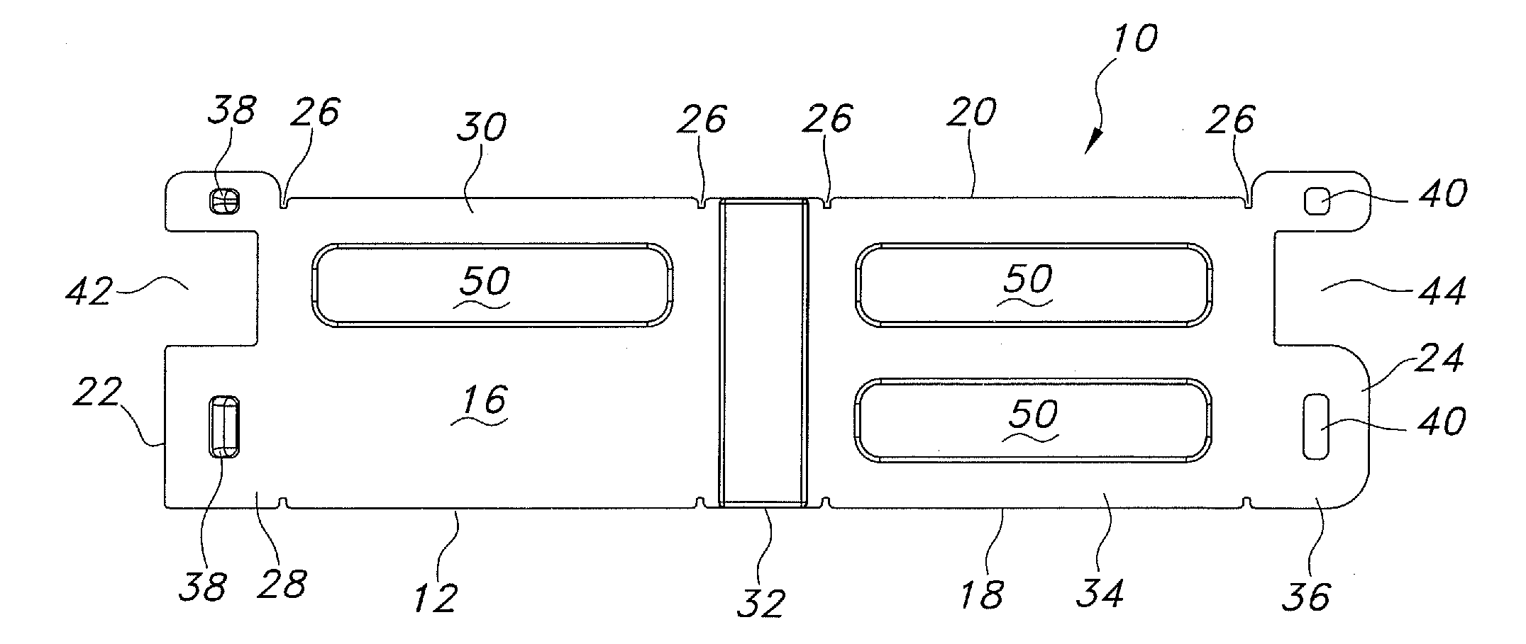
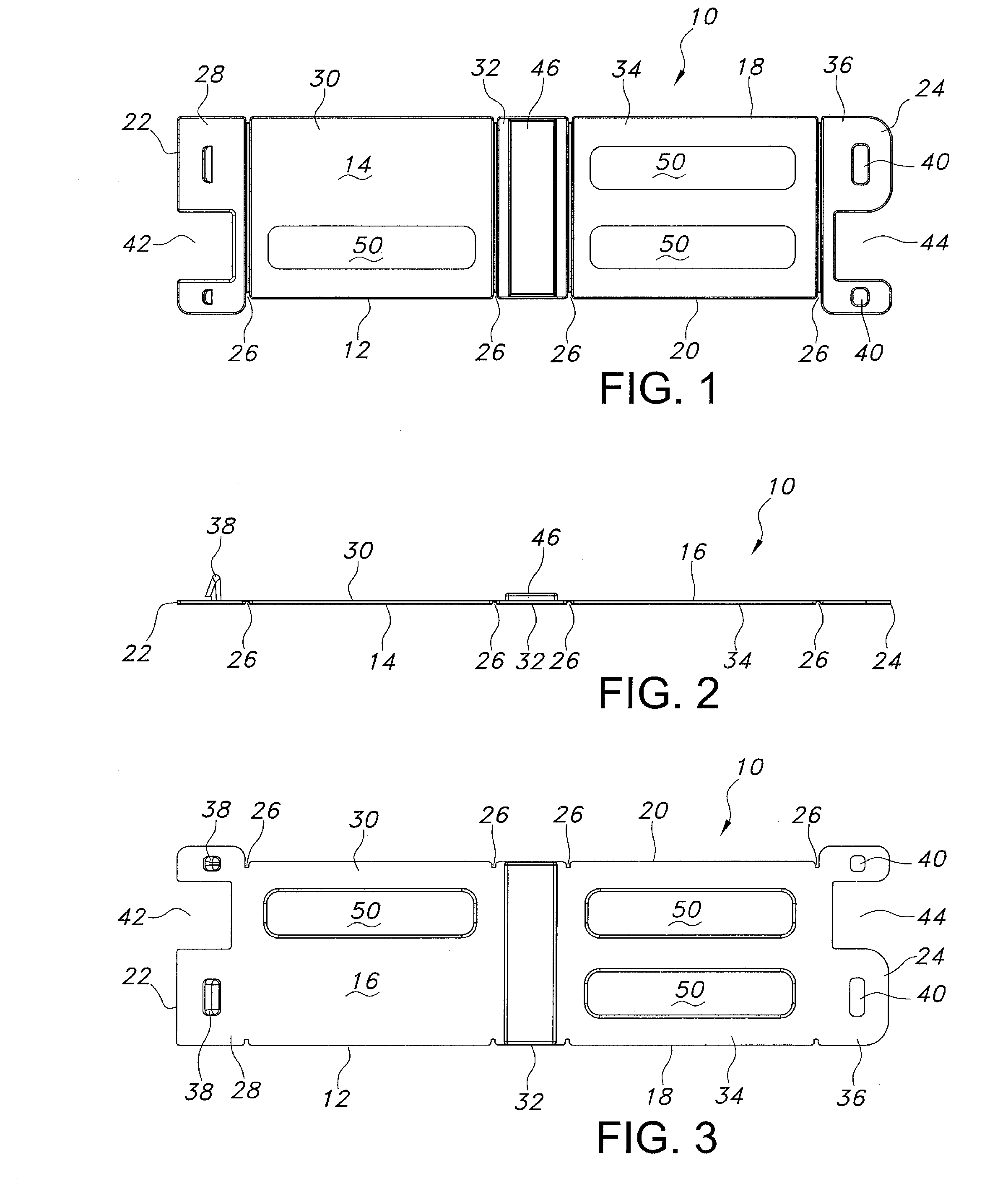
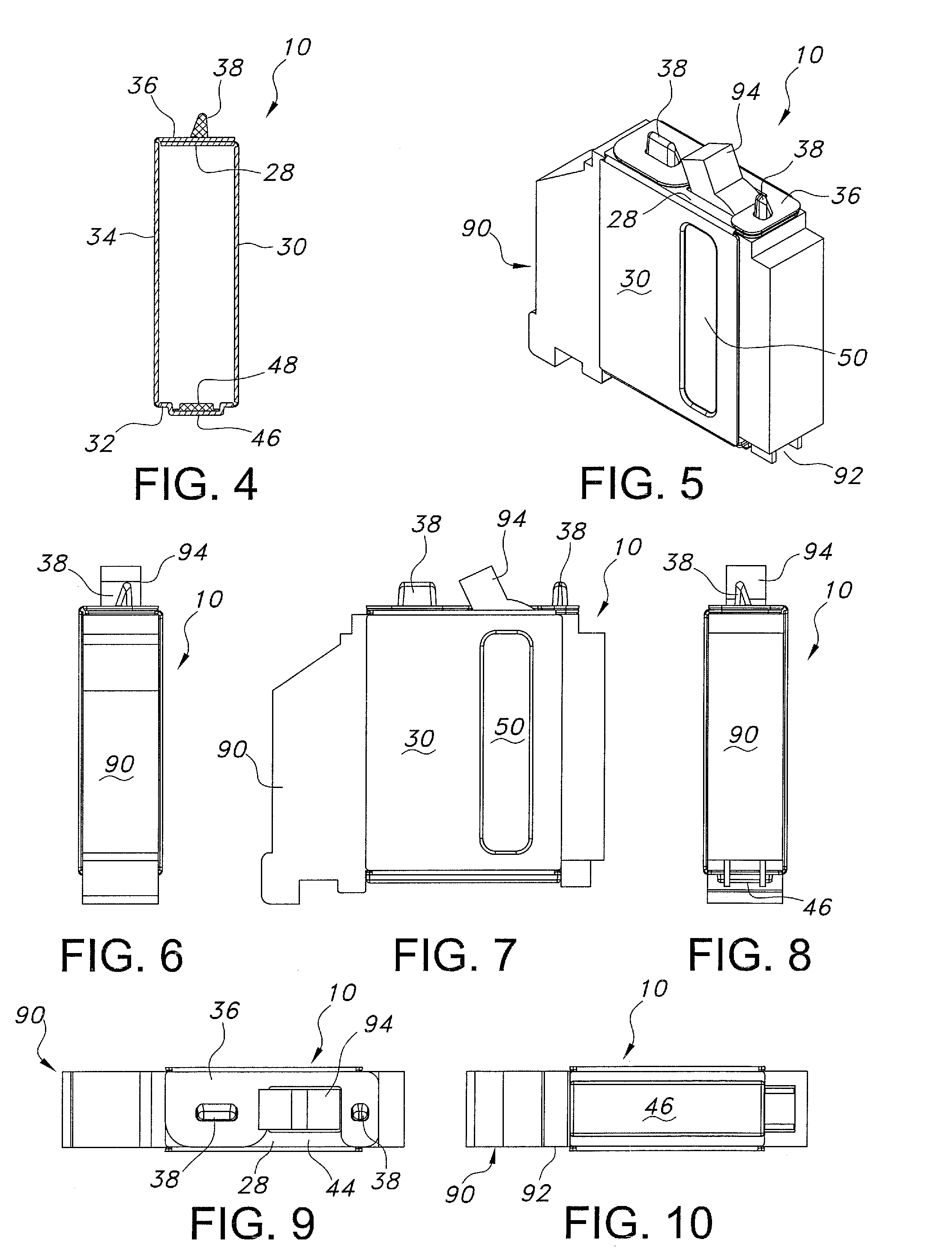
[0026]The tag is attached to a circuit breaker to provide identification and security. Typically, a circuit breaker has a rectangular block shape with opposing, substantially flat side walls, end walls and top and bottom walls, but no apertures that can be used as an attachment point for a tag. The top wall generally has a switch for resetting the circuit breaker after it trips. Due to its structure, it is difficult to attach a tag to a circuit breaker without using an adhesive, which can be troublesome for the purchaser to completely remove. To overcome these problems, the tag of the present invention wraps around the top, bottom and sides of the circuit breaker and is secured in place by one or more catches and notches in the two top sections that capture the circuit breaker switch. The tag is constructed from a plastic material, such as polypropylene, polyethylene or polyvinyl chloride. However, other types of plastic materials can be used and the plastic material used does not l...


PUM


Abstract

A tag for attachment to a circuit breaker is formed from a sheet of plastic material having first and second notches, one or more catches corresponding to one or more apertures, an electronic security device and a plurality of parallel grooves extending between the edges to form a plurality of sections. The tag is assembled by folding the sheet of plastic material so that the end sections overlap and the apertures fixedly receive the catches to secure the tag in a closed position. The notches in the first and second top sections form an opening, which is adapted for receiving the circuit breaker switch.

Description

[0001]This application claims priority from provisional application Ser. No. 61 / 504,938, filed on Jul. 6, 2011, which is incorporated herein in its entirety.FIELD OF THE INVENTION[0002]The present invention relates generally to tags attached to electrical devices. More particularly, the present invention relates to a tag that may be applied to a circuit breaker.BACKGROUND OF INVENTION[0003]Electronic tags attached to articles have a wide variety of uses, including tracking, inventory control and security. These electronic tags can also provide electronically readable information pertaining to the articles.[0004]These tags or markers may include radio frequency identification (RFID) tags or electronic article surveillance (EAS) tags. EAS tags may be used with an alarm system to provide theft deterrence by monitoring the location of the tags and any unauthorized movement of the article containing the EAS tag from a predetermined area. The tags can be enclosed in or attached to a varie...

Claims


Application Information

Patent Timeline
IPC IPC(8): G09F3/06
CPCG06K19/07758H01H9/18H01H2300/032H01H71/06
Inventor KOLTON, CHESTERNORMAN, MICHAELSTRASSBURGER, JAKETETIYEVSKY, ALEX
Owner B G PLASTICS
Why Eureka
Try Eureka