
Spindle motor

a spindle motor and spindle body technology, applied in the field of spindle motors, can solve the problems of increasing the pressure in the bearing clearance formed by the lower surface of the sleeve and the cover member, hindering the increase in pressure, and increasing the pressure in the bearing clearance, so as to reduce the floating time of the shaft

Inactive Publication Date: 2013-01-10
SAMSUNG ELECTRO MECHANICS CO LTD
View PDF11 Cites 1 Cited by
  • Summary
  • Abstract
  • Description
  • Claims
  • Application Information

AI Technical Summary

Benefits of technology

This patent describes a spindle motor that reduces the time it takes for the shaft to start moving. The motor also has a hole that helps the part that opens and closes easily fit in.

Problems solved by technology

However, at the time of initial driving of the shaft, an increase in pressure in the bearing clearance formed by the lower surface of the sleeve and the cover member may be hindered by the circulation hole formed in the sleeve.
That is, at the time of initial driving of the shaft, the lubricating fluid is introduced into the bearing clearance formed by the lower surface of the sleeve and the cover member, such that pressure in the bearing clearance increases; however, the lubrication fluid may be introduced into the circulation hole, such that the increase in pressure is hindered.

Method used


Image

  • Spindle motor
  • Spindle motor
  • Spindle motor

Examples


Embodiment Construction

[0028]Embodiments of the present invention will now be described in detail with reference to the accompanying drawings. However, it should be noted that the spirit of the present invention is not limited to the embodiments set forth herein and those skilled in the art and understanding the present invention can easily accomplish retrogressive inventions or other embodiments included in the spirit of the present invention by the addition, modification, and removal of components within the same spirit, but those are construed as being included in the spirit of the present invention.

[0029]Further, when it is determined that the detailed description of the known art related to the present invention may obscure the gist of the present invention, the detailed description thereof will be omitted.

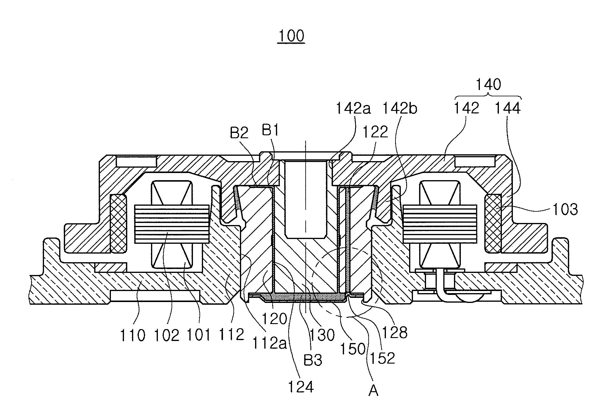
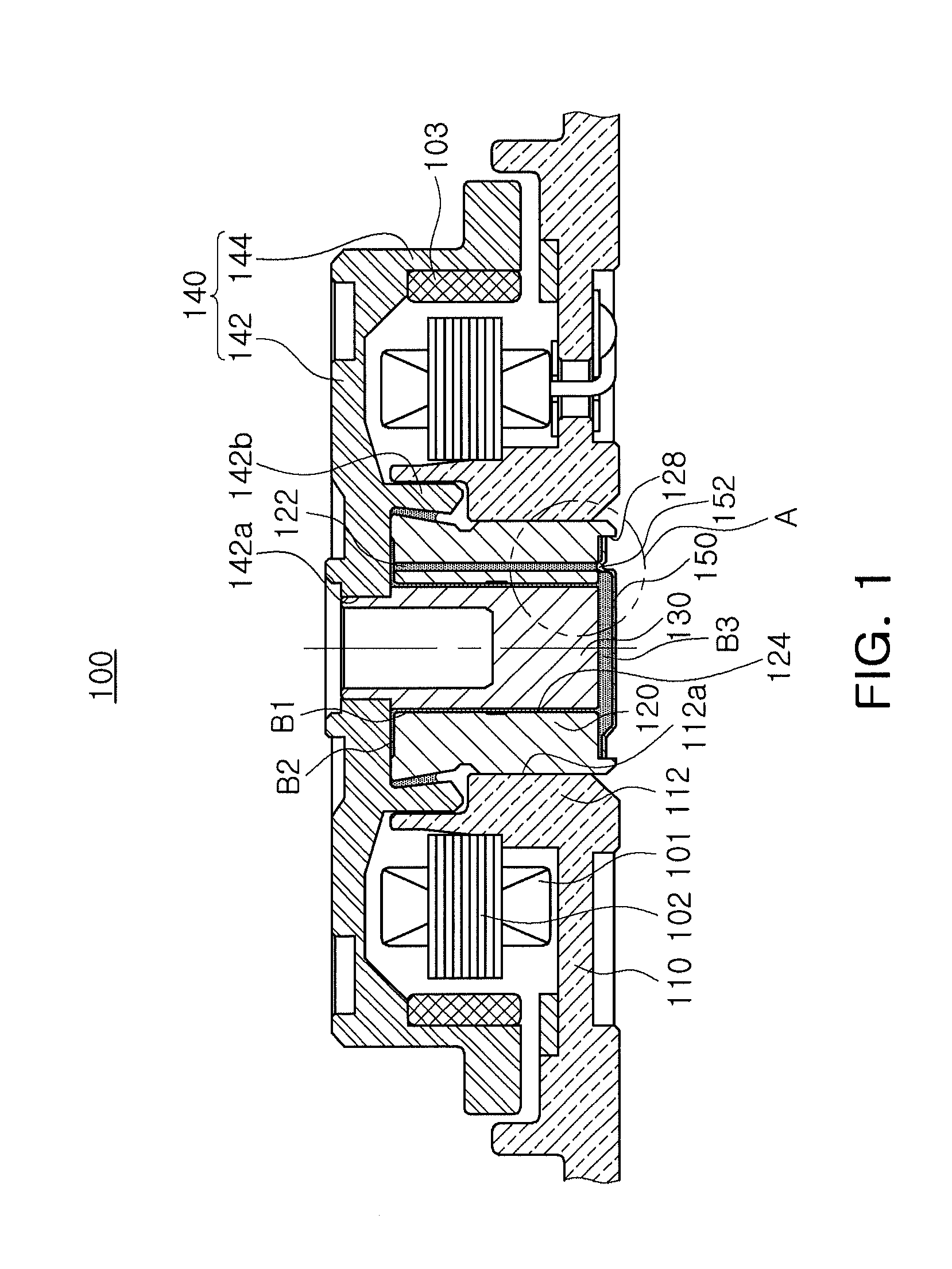
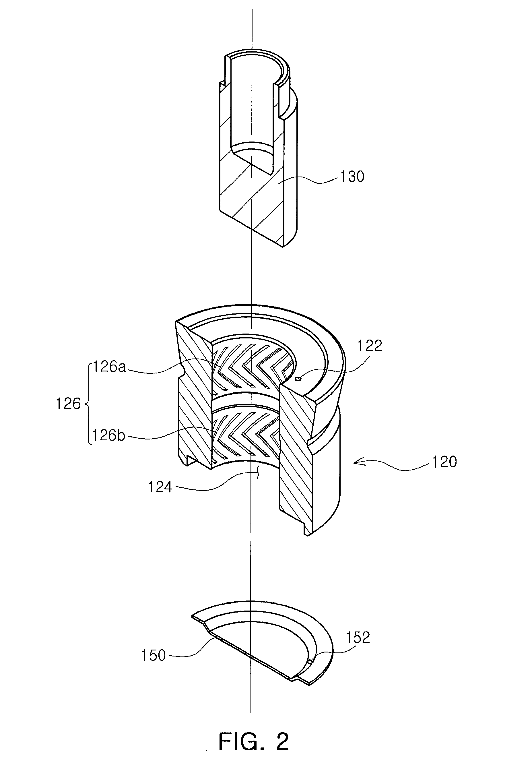
[0030]FIG. 1 is a cross-sectional view schematically showing a spindle motor according to an embodiment of the present invention; FIG. 2 is a partially cut-away, exploded perspective view showing a...


PUM


Abstract

There is provided a spindle motor including: a sleeve including a shaft rotatably mounted therein and a circulation hole formed therein; and a cover member mounted on a lower end portion of the sleeve and including an opening / closing part opening and closing the circulation hole.

Description

CROSS-REFERENCE TO RELATED APPLICATIONS[0001]This application claims the priority of Korean Patent Application No. 10-2011-0066002 filed on Jul. 4, 2011, in the Korean Intellectual Property Office, the disclosure of which is incorporated herein by reference.BACKGROUND OF THE INVENTION[0002]1. Field of the Invention[0003]The present invention relates to a spindle motor, and more particularly, to a spindle motor including a cover member.[0004]2. Description of the Related Art[0005]A small spindle motor used in a hard disk drive (HDD) is generally provided with a fluid dynamic bearing assembly, and a bearing clearance formed between a shaft and a sleeve configuring the fluid dynamic bearing assembly is filled with a lubricating fluid such as oil. The lubricating fluid filling the bearing clearance generates fluid dynamic pressure while being pumped, thereby rotatably supporting the shaft.[0006]Meanwhile, a bearing clearance may also be formed between an upper surface of the sleeve and ...

Claims


Application Information

Patent Timeline
Patent Type & Authority Applications(United States)
IPC IPC(8): H02K7/08
CPCH02K5/1675F16C33/103F16C17/107F16C2370/12G11B19/20G11B33/02
Inventor LEE, DONG HYUN
Owner SAMSUNG ELECTRO MECHANICS CO LTD
Learn More