Shock and impact testing device and method

a testing device and impact technology, applied in the direction of instruments, structural/machine measurement, material analysis, etc., can solve the problems of wasting a lot of time during testing and shortened the lifetime of the shock and impact testing devi

Inactive Publication Date: 2013-01-17
HONG FU JIN PRECISION IND (SHENZHEN) CO LTD +1
View PDF3 Cites 9 Cited by
  • Summary
  • Abstract
  • Description
  • Claims
  • Application Information

AI Technical Summary

Problems solved by technology

Thus, much time may be wasted during test and the lifetime of the shock and impact testing device may be shortened because of the repeated impact process.

Method used


Image

  • Shock and impact testing device and method
  • Shock and impact testing device and method
  • Shock and impact testing device and method

Examples


Embodiment Construction

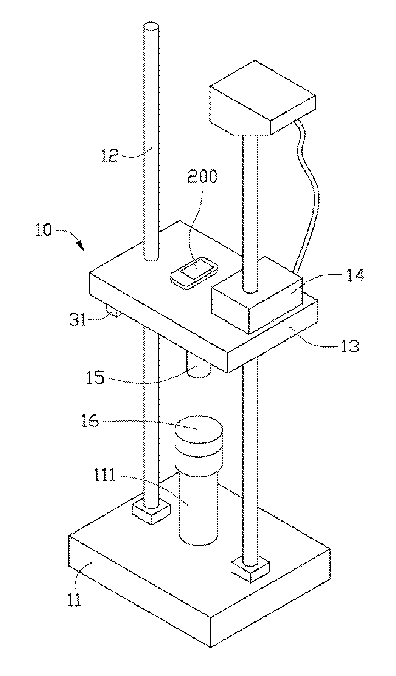
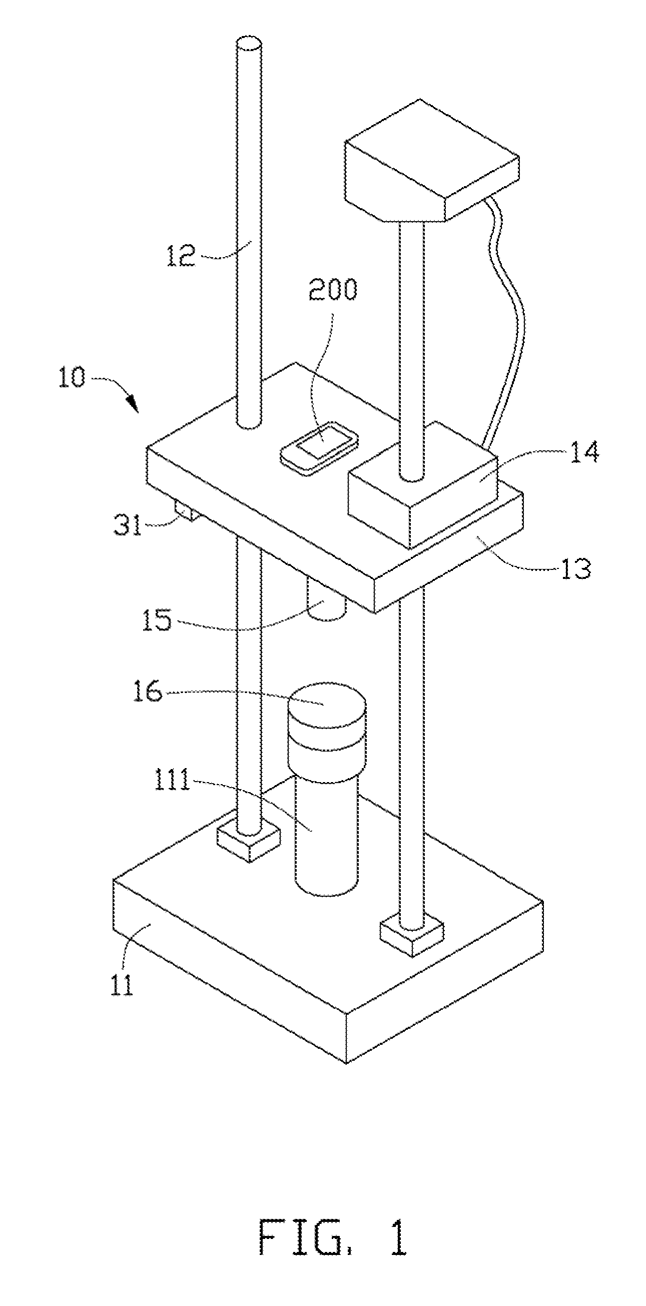
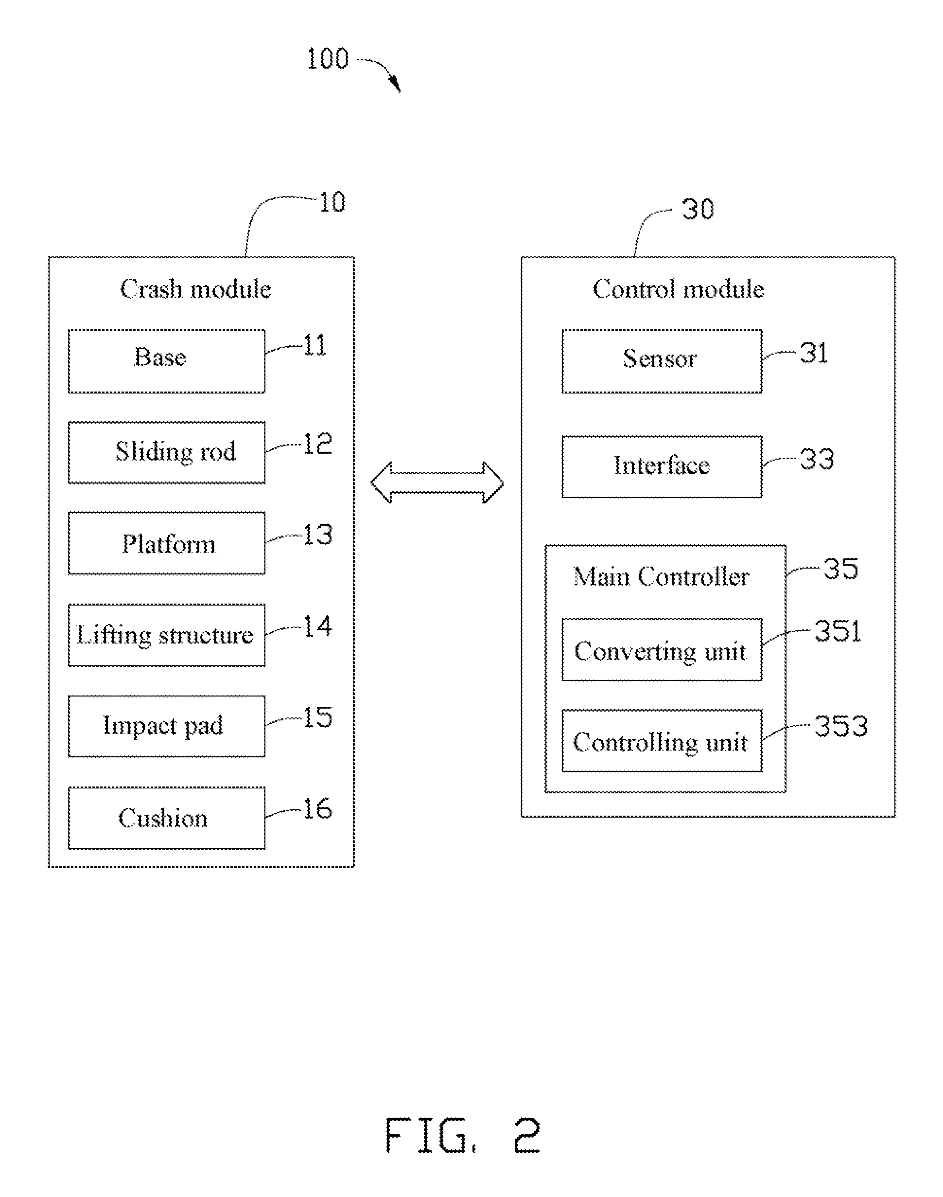
[0011]Referring to FIGS. 1 and 2, an exemplary embodiment of shock and impact testing device 100 includes a shock and impact module 10 and a control module 30 electrically connected to the shock and impact module 10. The shock and impact testing device 100 is used to execute shock and impact testing for an electronic device 200.

[0012]The shock and impact module 10 includes a base 11, a plurality of sliding rods 12, a platform 13, a lifting structure 14 (schematically shown), an impact pad 15, and a cushion 16. A securing block 111 is positioned on the base 11 to securely position the cushion 16. In this embodiment, there are two sliding rods 12, the two sliding rods 12 are parallel to each other and perpendicularly arranged on the base 11. The platform 13 is configured for supporting the electronic device 200. The sliding rods 12 extend through the platform 13, thus the platform 13 can slide along the sliding rods 12 to be close to or spaced from the base 11. The lifting structure 1...


PUM

PropertyMeasurementUnit
heightaaaaaaaaaa
total weightaaaaaaaaaa
linear restoring force coefficientaaaaaaaaaa

Abstract

A shock and impact testing device includes a shock and impact module and a control module. The shock and impact module includes a base, a platform, an elastic cushion positioned on the base, an elastic impact pad positioned on the platform facing the cushion, and a lifting structure connected to the platform to drive the platform to rise and then release the platform to allow the platform to fall down until the impact pad hits the cushion. The control module includes an interface configured for inputting impact parameters, a converting unit and a control unit. The converting unit calculates corresponding testing parameters according to the impact parameters. The control module controls the lifting structure to drive the platform to rise according to the testing parameters.

Description

BACKGROUND[0001]1. Technical Field[0002]The disclosure generally relates to shock and impact testing devices and methods, and particularly to a shock and impact testing device and method for electronic devices such as mobile phones.[0003]2. Description of Related Art[0004]During the manufacture of electronic devices such as mobile phones, shock and impact testing is commonly executed to verify assembly qualities of the electronic devices. A typical shock and impact testing device includes a platform, an impact pad, a cushion and a lifting structure. The platform is configured for supporting the electronic device. The impact pad and the cushion are elastic. The impact pad is positioned on one side of the platform, opposite to the cushion. The lifting structure drives the platform to rise to a height and then release the platform. The platform falls downwards until the impact pad hits the cushion to simulate a shock and impact situation to test the electronic device.[0005]During testi...

Claims


Application Information

Patent Timeline
Patent Type & Authority Applications(United States)
IPC IPC(8): G01N3/30
CPCG01M7/08
Inventor ZHAI, DI-GANGWEN, GUANG-MINGLIU, YUAN-WANG
Owner HONG FU JIN PRECISION IND (SHENZHEN) CO LTD
Why Eureka
Try Eureka