
Power gating control module, integrated circuit device, signal processing system, electronic device, and method therefor

a power gating control and integrated circuit technology, applied in the direction of power consumption reduction, pulse technique, instruments, etc., can solve the problems of power leakage becoming an increasingly significant part of the total exceeding the dynamic power consumption of the device, and not addressing power consumption

Inactive Publication Date: 2013-01-17
NXP USA INC
View PDF5 Cites 38 Cited by
  • Summary
  • Abstract
  • Description
  • Claims
  • Application Information

AI Technical Summary

Benefits of technology

The invention described in this patent has specific technical effects that will be explained below.

Problems solved by technology

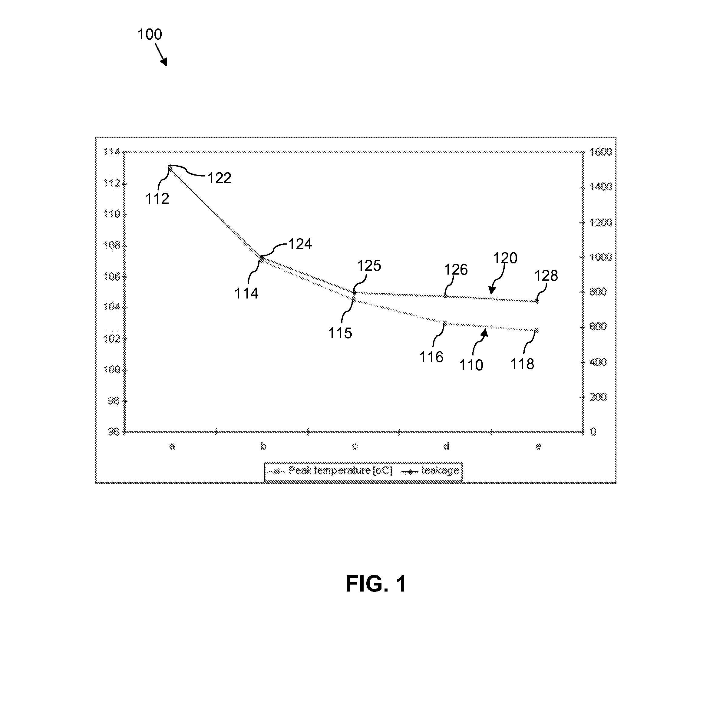
With the use of such high-leakage process semiconductor devices, power leakage becomes an increasingly significant part of the total power consumption of a device, and in some instances can exceed the dynamic power consumption of the device.
Accordingly, whilst DVFS enables the dynamic power consumption of a system to be reduced, it does not address power consumption resulting from high-leakage.
Thus, use of DVFS may not be sufficient to enable such high-leakage process semiconductor devices to meet the stringent power consumption requirements for a particular system.
Nevertheless, waking up a functional block that has been powered down using SRPG still involves a degree of latency, and also involves an energy overhead in charging and discharging capacitances and the like.
As such, whilst it is desirable to use SRPG to power down functional blocks within an integrated circuit device as much as possible, in order to maximise the reduction in power consumption, over-use of such a technique may result in a significant degradation in the performance of the system.
It may also negate some of the reduction in power consumption due to the energy overhead in charging and discharging capacitances.

Method used


Image

  • Power gating control module, integrated circuit device, signal processing system, electronic device, and method therefor
  • Power gating control module, integrated circuit device, signal processing system, electronic device, and method therefor
  • Power gating control module, integrated circuit device, signal processing system, electronic device, and method therefor

Examples


Embodiment Construction

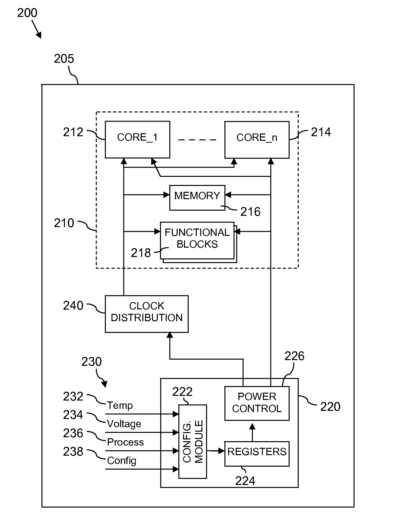
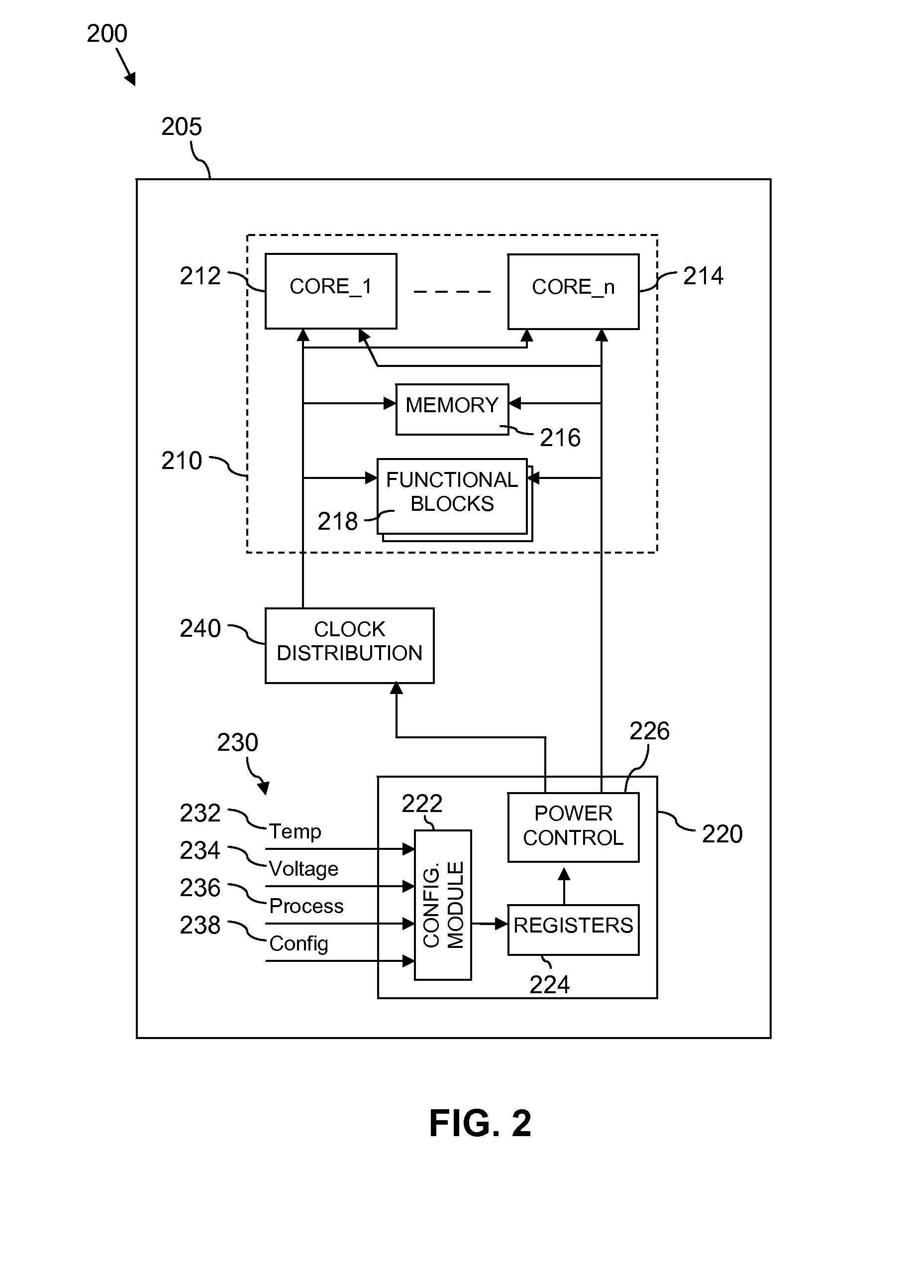
[0016]The present invention will now be described with reference to a power gating control module arranged to control gating of one or more power supplies to one or more parts of a signal processing system within an integrated circuit device. In particular, examples of the present invention will be described with reference to a power gating control module comprising generally integrated functional elements. However, it will be appreciated that the functional elements for providing the power gating control module are not limited to being provided within in a single functional module.

[0017]Furthermore, because the illustrated examples may for the most part, be implemented using electronic components and circuits known to those skilled in the art, details will not be explained in any greater extent than that considered necessary as illustrated below, for the understanding and appreciation of the underlying concept of the present invention and in order not to obfuscate or distract from ...


PUM


Abstract

An integrated circuit device comprising at least one signal processing module and a power gating control module arranged to control gating of at least one power supply to at least a part of the at least one signal processing module. The power gating control module is arranged to receive at least one operating parameter; configure at least one power gating setting of the power gating control module based at least partly on the at least one received operating parameter; and apply power gating for at least part of the at least one signal processing module in accordance with the at least one configured power gating setting.

Description

FIELD OF THE INVENTION[0001]The field of this invention relates to a power gating control module, an integrated circuit device, a signal processing system, an electronic device and a method therefor.BACKGROUND OF THE INVENTION[0002]In the field of integrated circuit devices, and in particular in the field of application processor integrated circuit devices, modern integrated circuit devices are, on the one hand, required to provide increasingly high performance whilst on the other hand required to fulfil increasingly stringent power consumption and thermal energy dissipation requirements.[0003]Dynamic voltage and frequency scaling (DVFS) is a known technique that attempts to achieve a balance between good system performance and reduced power consumption of an electronic device. DVFS allows ‘on-the-fly’ voltage and clock frequency adjustment according to the active needs of the system at that time. By reducing the voltage and / or clock frequency for a device, or part of a device, when...

Claims


Application Information

Patent Timeline
IPC IPC(8): H03K17/56
CPCG06F1/3203H03K19/0016Y02B60/1239G06F1/3287Y02B60/1282G06F1/3243Y02D10/00
Inventor PRIEL, MICHAELROZEN, ANTONSHOSHANY, YOSSI
Owner NXP USA INC
Learn More