Soft suture anchor made of braided or monofilament suture

Inactive Publication Date: 2013-01-17
LINVATEC
View PDF17 Cites 160 Cited by
  • Summary
  • Abstract
  • Description
  • Claims
  • Application Information

AI Technical Summary

Benefits of technology

[0008]In accordance with various embodiments of the present invention, a soft suture anchor is described that can reliably provide an increased diameter in a deployed condition for the c

Problems solved by technology

Similarly, the quality of installat

Method used


Image

  • Soft suture anchor made of braided or monofilament suture
  • Soft suture anchor made of braided or monofilament suture
  • Soft suture anchor made of braided or monofilament suture

Examples


first embodiment

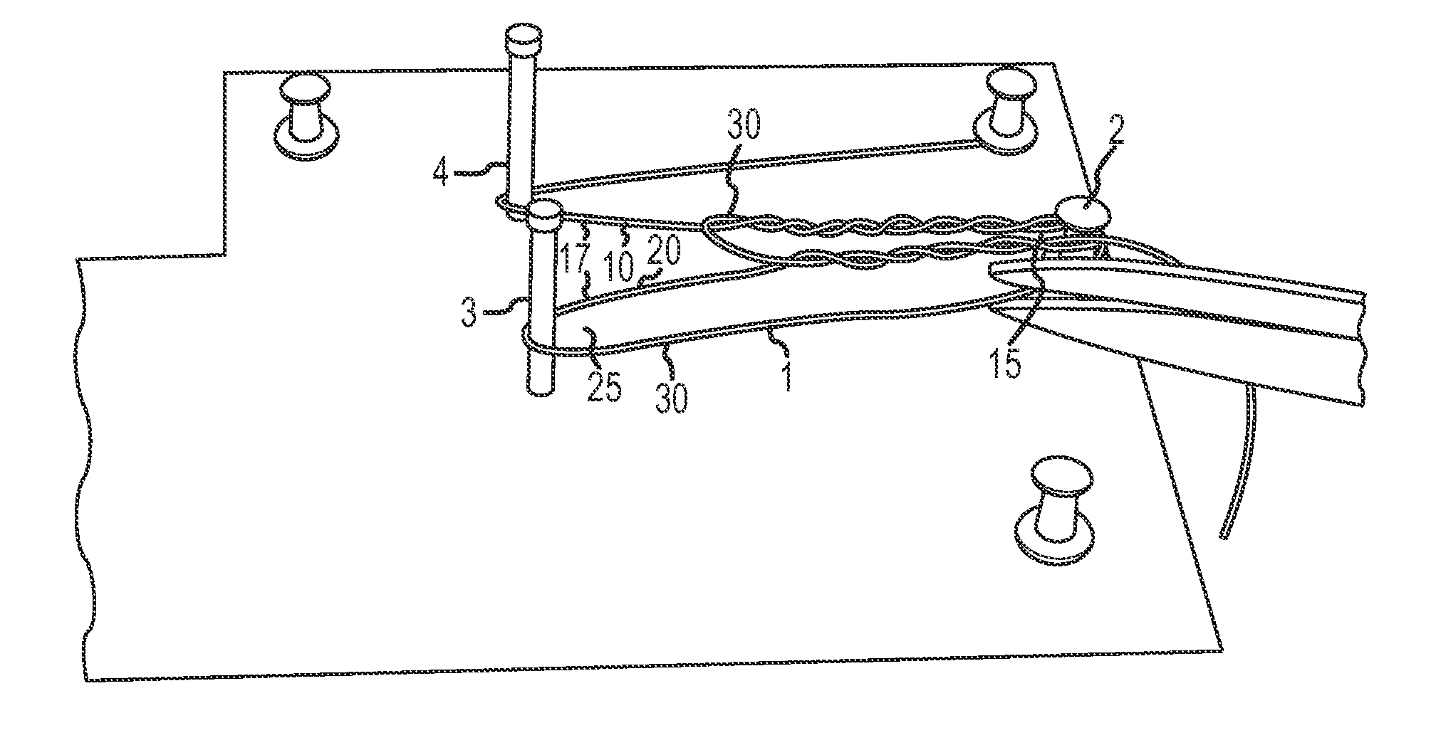
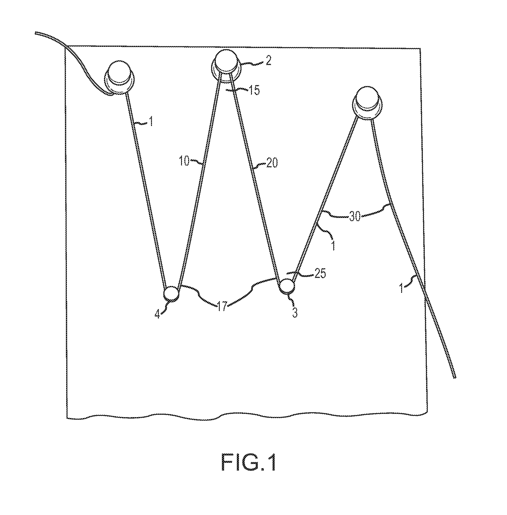
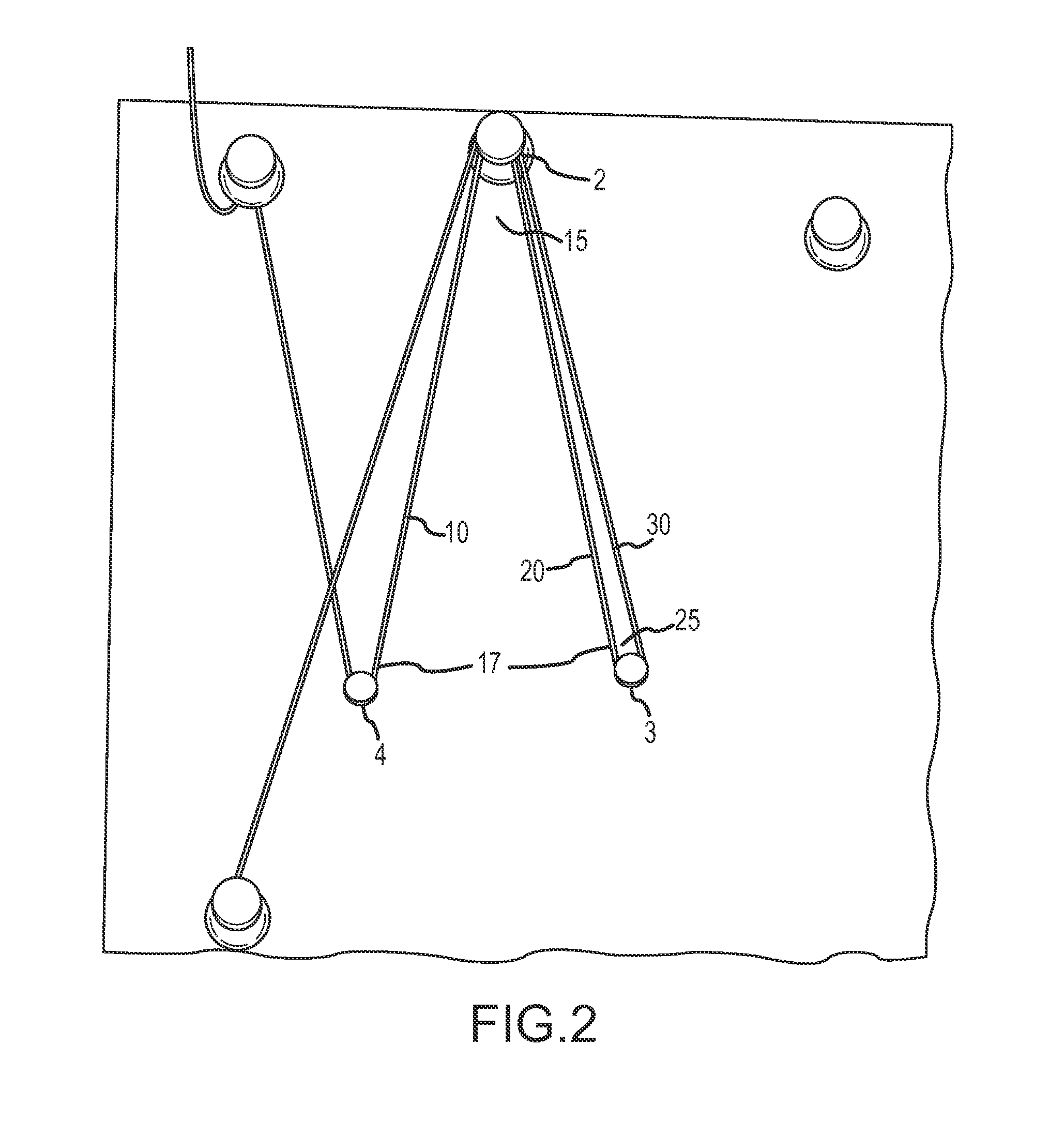
[0042]FIGS. 1-6 disclose a method of manufacturing a soft suture anchor from a single, continuous length of suture 1. Generally, the suture anchor of this first embodiment is created by arranging a suture in a predetermined manner designed to create a construct in which a portion of a First Section is slidably contained within a portion of a Second Section, the First Section and the Second Section being initially arranged in relation to one another as a single length of suture. More specifically, the Second Section is arranged in a manner around or surrounding a portion of the First Section with the two Sections being connected as part of a single length of suture. Once the desired arrangement of the Second Section about the First Section is completed, the construct may be cut, thereby separating the First Section and the Second Section, a portion of the First Section being slidably contained within the Second Section.

[0043]While not necessary for understanding the manufacturing ste...

second embodiment

[0062]FIGS. 7-14 disclose a method of manufacturing a variation of a soft suture anchor in accordance with a second embodiment. Portions of the method disclosed in FIGS. 7-14 are applicable to and representative of variations to the manufacturing method and anchor of the first embodiment.

[0063]Please note that because of the close relationship between the first and second embodiments, the names and reference numbers will be similar. It may be helpful to note that the method of the second embodiment may be used in place of the method of the first embodiment if there is a need or benefit to using a separate type (i.e., size, braid, material, color, etc.) of suture for the Second Section 30 than used in the First Section (i.e., first Standing End 10, Vertex 15, second Standing End 20).

[0064]FIG. 7 shows the first step of forming a suture anchor in accordance with an embodiment of the present invention. A length of suture material is arranged about a center pin 2 to form a first Vertex ...

third embodiment

[0075]As shown in FIG. 15, a First Section (a first Standing End 10, a Vertex 15, and a second Standing End 20) are likely separate from a Second Section 30 during forming. In relation to the second embodiment, instead of wraps 32 (FIGS. 8-14), the first Standing End 10 and the second Standing End 20 each pierce through Second Section 30 near a midpoint of the Second Section 30. In relation to the first embodiment, the piercing of the Second Section 30 would take place where the Second Section 30 is passed across the acute angle 17 to the second Standing End 20.

[0076]While this “piercing” of the Second Section 30 with the each of the Standing Ends 10, 20, this feature may be used in other embodiments, in this or some other form, for the purpose of maintaining equal lengths of Second Section 30 on either side of the Standing Ends, for example.


PUM


Abstract

A soft suture anchor is described that includes a first section of suture bent to define a first vertex separating a first standing end and a second standing end. The first standing end and the second standing end being legs of an acute angle. A second section of suture circumscribes the first standing end and the second standing end with at least one wrap. A first end of said second section is wrapped a plurality of times about the first standing end, and a second end of the second section is wrapped a plurality of times about the second standing end.

Description

CROSS REFERENCE TO RELATED APPLICATIONS[0001]This application is a non-provisional of and claims the benefit of priority from the following U.S. Provisional Patent Applications: (i) Ser. No. ZL61 / 517,230, entitled “Suture anchor made from one continuous filament”, and filed on Apr. 15, 2011; (ii) Ser. No. 61 / 517,221, entitled “Filament suture anchor formed with driver”, and filed on Apr. 15, 2011; (iii) Ser. No. 61 / 517,203, entitled “Soft distendable suture anchor”, and filed on Apr. 15, 2011. The content of each of the above-identified applications is incorporated herein by reference in its entirety.FIELD OF THE INVENTION[0002]The present invention is related to a suture anchor made entirely of braided or monofilament suture.BACKGROUND OF THE INVENTION[0003]Suture anchors are commonly employed during surgical procedures to provide a reliable attachment location for sutures in or against a substrate, those attached sutures then being used to capture and retain other objects, such as...

Claims


Application Information

Patent Timeline
IPC IPC(8): A61B17/06
CPCA61B2017/06171A61B17/06166
Inventor LOMBARDO, GIUSEPPEFITTS, STEVEN E.DEEB, JEAN-PAULMILLER, PETER C.
Owner LINVATEC
Why Eureka
Try Eureka