Vibration gyro element, gyro sensor, and electronic apparatus

a technology of vibration gyro and gyro sensor, which is applied in the direction of acceleration measurement using interia force, instruments, devices using electric/magnetic means, etc., can solve the problems of difficult improvement of detection sensitivity and difficulty in improving detection sensitivity by increasing exciting force, so as to achieve higher detection sensitivity, higher performance, and the effect of high accuracy

Active Publication Date: 2013-01-24
SEIKO EPSON CORP
View PDF6 Cites 14 Cited by
  • Summary
  • Abstract
  • Description
  • Claims
  • Application Information

AI Technical Summary

Benefits of technology

[0013]An advantage of some aspects of the invention is to improve a vibration gyro element including drive vibrating arms extending from a support part in juxtaposition and detection vibrating arms extending toward an opposite side to the drive vibrating arms in juxtaposition in detection sensitivity by increasing exciting force to the detection vibrating arms.
[0017]By setting the resonance frequencies fd, fp1, fp2 in the above described manner, the respective detection vibrating arms flexurally vibrate in the same phase in the first detection mode and the second detection mode and the exciting force acting on the respective detection vibrating arms is increased by the vibration in the first and second detection modes, and the detection sensitivity may be improved.
[0025]According to yet another aspect of the invention, with the vibration gyro element of the aspect of the invention, an electronic apparatus with higher performance and higher accuracy including a sensor device such as a gyro sensor with higher detection sensitivity may be provided.

Problems solved by technology

However, any of the above described vibration gyros in related art has only one vibration mode for detection, and it is not easy to improve the detection sensitivity by increasing the exciting force to the detection vibrating arm.
Especially, as the vibration gyro element is made smaller in size, also the drive and detection vibrating arms are made smaller, and the improvement of the detection sensitivity by increasing the exciting force becomes more difficult.

Method used


Image

  • Vibration gyro element, gyro sensor, and electronic apparatus
  • Vibration gyro element, gyro sensor, and electronic apparatus
  • Vibration gyro element, gyro sensor, and electronic apparatus

Examples


Embodiment Construction

[0034]As below, preferred embodiments of the invention will be explained with reference to the accompanying drawings. Note that, in the accompanying drawings, the same and similar component elements have the same or similar reference signs.

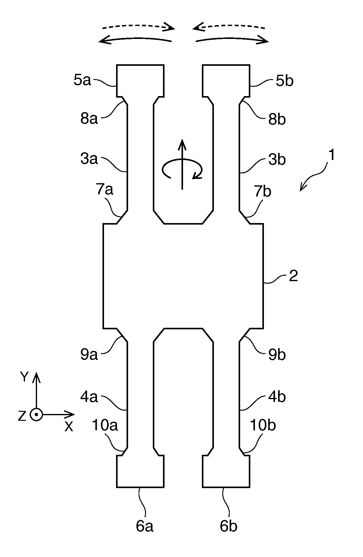
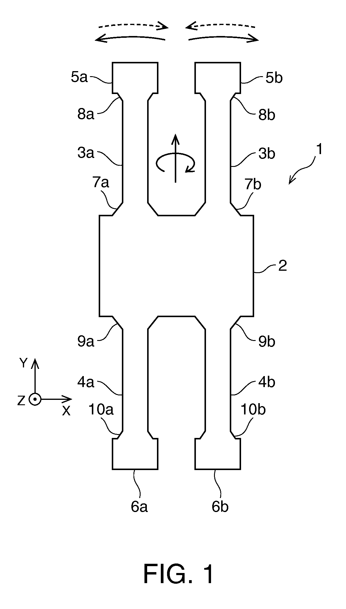
[0035]FIG. 1 schematically shows a vibration gyro element 1 of a first embodiment of the invention used for an angular velocity sensor, for example. The vibration gyro element 1 includes a double-tuning fork vibrating reed and has a support part 2 having a nearly rectangular shape at the center, a pair of drive vibrating arms 3a, 3b extending from the support part toward one side in juxtaposition in parallel, and a pair of detection vibrating arms 4a, 4b extending to the opposite side in juxtaposition in parallel. Spindle parts 5a, 5b, 6a, 6b are provided at ends of the respective vibrating arms so that, even when their lengths are made shorter, generation in higher order vibration modes may be suppressed and the vibration frequencies may be stabi...


PUM


Abstract

A vibration gyro element includes drive vibrating arms and detection vibrating arms at the opposite side, and has a first detection mode in which the drive vibrating arms flexurally vibrate oppositely to each other in an out-of-plane direction in an opposite phase to an action direction of Coriolis force and the detection vibrating arms flexurally vibrate oppositely to each other in the out-of-plane direction in an opposite phase to that of the drive vibrating arms, and a second detection mode in which the drive vibrating arms flexurally vibrate oppositely to each other in the out-of-plane direction in the same phase as the action direction of the Coriolis force and the detection vibrating arms flexurally vibrate oppositely to each other in the out-of-plane direction in the same phase as that of the drive vibrating arms.

Description

BACKGROUND[0001]1. Technical Field[0002]The present invention relates to a vibration gyro element using a flexing vibrating reed, and a gyro sensor and an electronic apparatus using the element.[0003]2. Related Art[0004]In related art, piezoelectric devices of piezoelectric vibrators, oscillators and real time clock modules with piezoelectric vibrating reeds and IC chips, etc. have been widely used as clock sources of electronic circuits for an electronic apparatus such as clocks, home appliances, various information and communication apparatuses, and an OA apparatus. Further, sensors of piezoelectric vibration gyros etc. using flexing vibrating reeds have been widely used for various electronic apparatuses such as digital still cameras, video cameras, navigation systems, vehicle position detectors, pointing devices, game controllers, cellular phones, and head-mounted displays for detection of physical quantities of angular velocities, angular acceleration, acceleration, forces, and...

Claims


Application Information

Patent Timeline
Patent Type & Authority Applications(United States)
IPC IPC(8): G01C19/5607
CPCG01C19/5607
Inventor SHIMURA, MASASHIKIKUCHI, TAKAYUKI
Owner SEIKO EPSON CORP
Why Eureka
Try Eureka